
Page 179 - Dynamics and Control of Nuclear Reactors
P. 179
176 CHAPTER 13 Boiling water reactors
CONTAINMENT
SPRAY
SHIELD BUILDING
125 TON CRANE W/15 TON AUX HOOK
CONTAINMENT
UPPER POOL
DRYWELL HEAD
FUEL TRANSFER
POOL
REACTOR VESSEL
REACTOR SHIELD
DRYWELL BOUNDRY
WEIR WALL DRYWELL
FUEL TRANSFER
S/R VALVE LINE
TUBE
SUPRESSION
POOL
HORIZONTAL
VENT
(C)
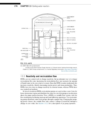
FIG. 13.5, cont’d
(C) BWR Mark III containment.
Courtesy of GE Hitachi Nuclear Energy Americas LLC (General electric advanced technology manual,
Chapter 6.2, BWR Primary Containments, U.S. Nuclear Regulatory Commission, https://www.nrc.gov/docs/
ML1414/ML14140A181.pdf).
13.5 Reactivity and recirculation flow
BWRs can use control rods to change reactivity, but an alternate way is to change
recirculation flow rate. Increasing the recirculation flow rate increases the amount
of liquid water in the core relative to steam. Since the BWR is under-moderated, this
increases reactivity, thereby increasing reactor power and steam production. Thus,
BWRs have two ways to change reactivity by external means, whereas PWRs have
one (control rod motion).
In forced circulation BWRs recirculation pumps are used to draw water from the
lower downcomer region and distribute the water to a set of jet pumps at an elevation
above the pump suction location. Thus, a BWR is a variable flow system, with the
flow modulation facilitating start-up and load-following operations. Two recirculat-
ing pumps distribute water to jet pumps, through a sparger ring. Changing the pump-
ing power (hence, the coolant flow rate) causes a change in reactivity through a
change in core voids. See Section 13.3.2 for a description of jet pump operation.