
Page 264 - Dynamics of Mechanical Systems
P. 264
0593_C08_fm Page 245 Monday, May 6, 2002 2:45 PM
Principles of Dynamics: Newton’s Laws and d’Alembert’s Principle 245
FIGURE 8.4.1
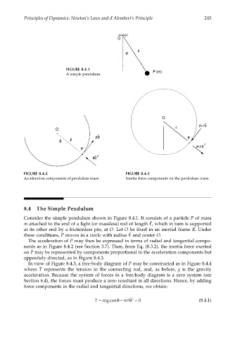
A simple pendulum.
O
θ
m ¨
P
m θ 2
FIGURE 8.4.2 FIGURE 8.4.3
Acceleration components of pendulum mass. Inertia force components on the pendulum mass.
8.4 The Simple Pendulum
Consider the simple pendulum shown in Figure 8.4.1. It consists of a particle P of mass
m attached to the end of a light (or massless) rod of length , which in turn is supported
at its other end by a frictionless pin, at O. Let O be fixed in an inertial frame R. Under
these conditions, P moves in a circle with radius and center O.
The acceleration of P may then be expressed in terms of radial and tangential compo-
nents as in Figure 8.4.2 (see Section 3.7). Then, from Eq. (8.3.2), the inertia force exerted
on P may be represented by components proportional to the acceleration components but
oppositely directed, as in Figure 8.4.3.
In view of Figure 8.4.3, a free-body diagram of P may be constructed as in Figure 8.4.4
where T represents the tension in the connecting rod, and, as before, g is the gravity
acceleration. Because the system of forces in a free-body diagram is a zero system (see
Section 6.4), the forces must produce a zero resultant in all directions. Hence, by adding
force components in the radial and tangential directions, we obtain:
T − mgcosθ − m θ ˙ 2 = 0 (8.4.1)
l