
Page 267 - Dynamics of Mechanical Systems
P. 267
0593_C08_fm Page 248 Monday, May 6, 2002 2:45 PM
248 Dynamics of Mechanical Systems
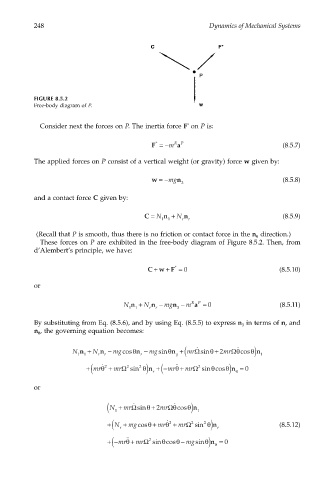
FIGURE 8.5.2
Free-body diagram of P.
Consider next the forces on P. The inertia force F on P is:
*
*
a
F =−m RP (8.5.7)
The applied forces on P consist of a vertical weight (or gravity) force w given by:
w =−mg n (8.5.8)
3
and a contact force C given by:
C = N n + N n (8.5.9)
11 r r
(Recall that P is smooth, thus there is no friction or contact force in the n direction.)
θ
These forces on P are exhibited in the free-body diagram of Figure 8.5.2. Then, from
d’Alembert’s principle, we have:
+
+
*
CwF = 0 (8.5.10)
or
N n + N n − mgn − m a = 0 (8.5.11)
RP
11 r r 3
By substituting from Eq. (8.5.6), and by using Eq. (8.5.5) to express n in terms of n and
3 r
n , the governing equation becomes:
θ
˙
N n + N n − mgcosθ n − mgsinθ n + mr ( Ω sinθ + 2 mr θ ˙ cosθ n 1 )
Ω
11 r r r q
θ
˙˙
+ mr ( θ 2 ˙ + mrΩ 2 sin 2 n +− ( mr +θ mrΩ 2 sin cosθ n ) θ = 0
r ) θ
or
1 (
˙
N + mr sinΩ θ + 2 mrΩθ ˙ cosθ 1 ) n
r (
+ N + mgcosθ + mrθ 2 ˙ + mrΩ 2 sin 2 r ) θ n (8.5.12)
+− ( mr +θ mrΩ 2 sin cosθ − mgsinθ n θ = 0
)
˙˙
θ