
Page 271 - Dynamics of Mechanical Systems
P. 271
0593_C08_fm Page 252 Monday, May 6, 2002 2:45 PM
252 Dynamics of Mechanical Systems
where (x, y, z) are the coordinates of G relative to the X-, Y-, Z-axes system of Figure 8.7.1.
Then, by substituting into Eq. (8.7.4), we obtain the scalar equations:
˙˙ x = 0 , ˙˙ y = 0 , ˙˙ z = − g (8.7.7)
These are differential equations governing the motion of a projectile. They are easy to
solve given suitable initial conditions. For example, suppose that initially (at t = 0) we
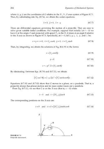
have G at the origin O and projected with speed V in the X–Z plane at an angle θ relative
O
to the X-axis as shown in Figure 8.7.3. Specifically, at t = 0, let x, y, z, , ˙ x y ˙ , and be:
˙ z
x = y = = 0, ˙ x V cos , ˙ y = 0, ˙ z V sinθ (8.7.8)
θ
=
=
z
O O
Then, by integrating, we obtain the solutions of Eq. (8.6.19) in the forms:
x = ( V cosθ t )
O (8.7.9)
y = 0 (8.7.10)
z =− gt 2 + V ( sin t ) θ (8.7.11)
2
O
By eliminating t between Eqs. (8.7.9) and (8.7.11), we obtain:
O (
V cos θ) =− ( g 2) x +( V sin cosθ) x (8.7.12)
θ
2
2
2
2
z
O
Equations (8.7.10) and (8.7.12) show that G moves in a plane, on a parabola. That is, a
projectile always has planar motion and its mass center traces out a parabola.
From Eq. (8.7.11), we see that G is on the X-axis (that is, z = 0) when:
t = 0 and t = (2 V g)sinθ (8.7.13)
O
The corresponding positions on the X-axis are:
θ
2
x = 0 and x = = (2 V g) sin cosθ (8.7.14)
d
O
FIGURE 8.7.3
Projectile movement.