Page 273 - Dynamics of Mechanical Systems
P. 273

0593_C08_fm  Page 254  Monday, May 6, 2002  2:45 PM


                       254                                                 Dynamics of Mechanical Systems


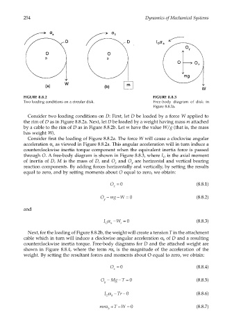
                       FIGURE 8.8.2                                           FIGURE 8.8.3
                       Two loading conditions on a circular disk.             Free-body diagram of disk in
                                                                              Figure 8.8.2a.

                        Consider two loading conditions on D: First, let D be loaded by a force W applied to
                       the rim of D as in Figure 8.8.2a. Next, let D be loaded by a weight having mass m attached
                       by a cable to the rim of D as in Figure 8.8.2b. Let m have the value W/g (that is, the mass
                       has weight W).
                        Consider first the loading of Figure 8.8.2a. The force W will cause a clockwise angular
                       acceleration α  as viewed in Figure 8.8.2a. This angular acceleration will in turn induce a
                                   a
                       counterclockwise inertia torque component when the equivalent inertia force is passed
                       through O. A free-body diagram is shown in Figure 8.8.3, where I  is the axial moment
                                                                                  O
                       of inertia of D, M is the mass of D, and O  and O  are horizontal and vertical bearing
                                                              x
                                                                     y
                       reaction components. By adding forces horizontally and vertically, by setting the results
                       equal to zero, and by setting moments about O equal to zero, we obtain:
                                                            O = 0                               (8.8.1)
                                                             x
                                                       O −  mg W = 0                            (8.8.2)
                                                               −
                                                         y
                       and

                                                         I α− W = 0                             (8.8.3)
                                                          O  a  r

                        Next, for the loading of Figure 8.8.2b, the weight will create a tension T in the attachment
                       cable which in turn will induce a clockwise angular acceleration α  of D and a resulting
                                                                                  b
                       counterclockwise inertia torque. Free-body diagrams for D and the attached weight are
                       shown in Figure 8.8.4, where the term  rα  is the magnitude of the acceleration of the
                                                             b
                       weight. By setting the resultant forces and moments about O equal to zero, we obtain:

                                                            O = 0                               (8.8.4)
                                                             x
                                                               −
                                                        O −  Mg T = 0                           (8.8.5)
                                                         y
                                                         I α−  Tr − 0                           (8.8.6)
                                                          O  b
                                                       mrα+  T W = 0                            (8.8.7)
                                                               −
                                                           b
   268   269   270   271   272   273   274   275   276   277   278