
Page 278 - Dynamics of Mechanical Systems
P. 278
0593_C08_fm Page 259 Monday, May 6, 2002 2:45 PM
Principles of Dynamics: Newton’s Laws and d’Alembert’s Principle 259
Observe that the unit vectors of the rods may be expressed in terms of the horizontal
and vertical unit vectors and in terms of each other as:
n = c n + s n , n = c n + s n
11 1 1 1 2 21 2 1 2 2
(8.10.4)
n =−s n + c n , n = −s n + c n
12 1 1 1 2 22 2 1 2 2
and
c
c
n = n − s n , n = n − s n
1 1 11 1 12 1 2 21 2 22
(8.10.5)
s
n =− n + c n , n = n + c n
s
2 1 11 1 12 2 2 21 2 22
and
n = c n − s n , n = c n + s n
−
−
−
−
11 2 1 21 2 1 22 21 2 1 11 2 1 12
(8.10.6)
n = s n + c n , n = −s n + c n
−
−
−
−
12 2 1 21 2 1 22 22 2 1 11 2 1 22
where s and c are abbreviations for sinθ and cosθ (i = 1, 2), respectively, and s and c i–j
i–j
i
i
i
i
are abbreviations for sin(θ – θ ) and cos(θ – θ ), respectively.
i
j
j
i
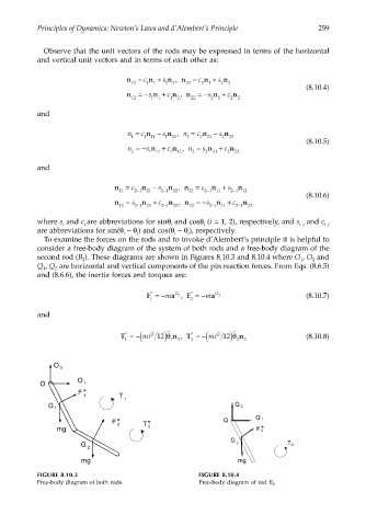
To examine the forces on the rods and to invoke d’Alembert’s principle it is helpful to
consider a free-body diagram of the system of both rods and a free-body diagram of the
second rod (B ). These diagrams are shown in Figures 8.10.3 and 8.10.4 where O , O and
1
2
2
Q , Q are horizontal and vertical components of the pin reaction forces. From Eqs. (8.6.5)
1
2
and (8.6.6), the inertia forces and torques are:
*
*
G
F =−m a , F =−m a G 2 (8.10.7)
1
1 2
and
˙˙
˙˙
*
*
T =−(ml 2 12)θ n , T =−(ml 2 12)θ n (8.10.8)
1 1 3 2 2 3
O 2
O
O 1
F *
T
1
1
G 1 Q 2
Q
F * T * Q 1
2
mg 2 F *
2
G
G 2 T 2
2
mg mg
FIGURE 8.10.3 FIGURE 8.10.4
Free-body diagram of both rods. Free-body diagram of rod B 2 .