
Page 283 - Dynamics of Mechanical Systems
P. 283
0593_C08_fm Page 264 Monday, May 6, 2002 2:45 PM
264 Dynamics of Mechanical Systems
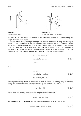
FIGURE 8.12.1 FIGURE 8.12.2
Rotating, pinned rod. Unit vectors of the shaft and rod.
line of S. Let B have length and mass m, and let the orientation of B be defined by the
angle θ as shown in Figure 8.12.1.
We can obtain the equation governing θ and, hence, the motion of B by proceeding as
in the previous examples. To this end, consider first the kinematics of B: Let unit vectors
n , n , n , n , and n be introduced as in Figure 8.12.2, where n is parallel to the pin axis
1 2 3 r θ r
of B and radial line of S; n is perpendicular to k and n ; and n , n , and n are mutually
θ
1
r
3
2
perpendicular dextral unit vectors, with n being parallel to n and n being along B, as
3 r 1
shown. Then, these unit vectors are related to each other by the expressions:
n =−cosθ k + sinθ n θ
1
n = sinθ k + cosθ n θ (8.12.1)
2
n = n r
3
and
n = n
r 3
n = sin θ n + cos θ n 2 (8.12.2)
θ
1
k =−cos θ n + sin θ n
1 2
The angular velocity ωω ωω of B in the inertia frame R in which S is rotating may be obtained
using the addition theorem for angular velocity (see Section 4.7). That is,
Ω
ωω= θn + k (8.12.3)
r
Then, by differentiating, we obtain the angular acceleration of B as:
˙
˙˙
˙
Ω
Ω
αα= θn r + θ n θ + k (8.12.4)
By using Eqs. (8.12.2) ωω ωω and αα αα may be expressed in terms of n , n , and n as:
1 2 3
˙
ωω= −Ωcosθn + Ωsinθn + θn (8.12.5)
1 2 3