
Page 284 - Dynamics of Mechanical Systems
P. 284
0593_C08_fm Page 265 Monday, May 6, 2002 2:45 PM
Principles of Dynamics: Newton’s Laws and d’Alembert’s Principle 265
and
)
)
θ
˙
˙˙
˙
θ
˙
θ
αα= ( Ω sinθ − Ω cosθ n 1 +( Ω cosθ + Ωsinθ n 2 + θn 3 (8.12.6)
˙
Assuming the shaft radius to be small, the velocity v and acceleration a of the mass center
G of B in the inertia frame R may be obtained from the expressions (see Eqs. (4.9.4) and
(4.9.6)):
v = ωω ×(l n ) 2 (8.12.7)
1
and
[
a = αα ×(l n ) 2 + ωω × ωω ×(l 2 n ) ] (8.12.8)
1 1
By substituting from Eqs. (8.12.5) and (8.12.6), v and a become:
v = ( ) 2 θ ˙ n −( ) 2 Ωs n (8.12.9)
l
l
2 θ 3
and
[
2 ˙
l 2 θ
n + ( ) −( ) 2 Ω sin cosθ
a =−( ) 2 Ω sin θ −( ) ] [ l 2 θ ˙˙ l 2 θ ] 2
2
2
l
n
1
[
˙
˙
˙
θ
θ
+−( ) 2 Ωcosθ −( ) 2 Ωsinθ −( ) 2 Ω cosθ ] n 3 (8.12.10)
l
l
l
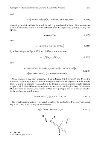
Next, consider a free-body diagram of B as in Figure 8.12.3, where F and T are the
*
*
force and couple torque, respectively, of an equivalent inertia force system, w is the weight
force, O is the pin reaction force, and N is the torque of the pin reaction couple. Because
the pin is frictionless, N has zero component in the direction of the pin axis n . To eliminate
3
O and N from the analysis, we can use d’Alembert’s principle and set moments about O
in the n direction equal to zero:
3
( [ l 2)n 1 × w +( l 2)n 1 × F * + T * ⋅n 3 ] = 0 (8.12.11)
The weight force w is simply –mgk and, as before, the inertia force F is –ma. Then, using
*
Eq. (8.12.2), Eq. (8.12.11) may be expressed as:
− ( ) 2 sinθ − ( )a + T = 0 (8.12.12)
l
mg l
m
2
2 3
FIGURE 8.12.3
A free-body diagram of rod B.