
Page 287 - Dynamics of Mechanical Systems
P. 287
0593_C08_fm Page 268 Monday, May 6, 2002 2:45 PM
268 Dynamics of Mechanical Systems
)
˙˙
˙˙
− ˙ ˙
˙˙
cos
+ sinθ θφθ n
αα= ( θψφθ n 1 +( ψ φ + ˙ ˙ cos ) 2
(8.13.4)
˙˙
˙ ˙
φθφθ
+( cos − ˙ ˙ sinθ ψθ
+ ) n
3
where n , n , and n are the unit vectors shown in Figure 8.13.1.
2
3
1
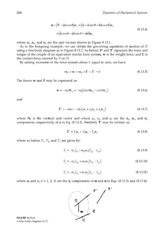
As in the foregoing example, we can obtain the governing equations of motion of D
*
using a free-body diagram as in Figure 8.13.2. As before, F and T represent the force and
*
torque of the couple of an equivalent inertia force system, w is the weight force, and C is
the contact force exerted by S on D.
By setting moments of the force system about C equal to zero, we have:
rn × w + rn × F + T = 0 (8.13.5)
*
*
3 3
The forces w and F may be expressed as:
mg
w =−mg N =− (sinθ n + cosθ n ) (8.13.6)
3 2 3
and
*
m
F =−m a =− (a n + a n + a n ) (8.13.7)
1 1 2 2 3 3
where N is the vertical unit vector and where a , a , and a are the n , n , and n 3
3
1
3
1
2
2
components, respectively, of a in Eq. (8.13.2). Similarly T may be written as:
*
*
T = T n + T n + T n (8.13.8)
1 1 2 2 3 3
where as before T , T , and T are given by:
3
1
2
2 (
T =−α I + ω ω I − ) (8.13.9)
I
1 1 11 3 22 33
3 (
T =−α I + ω ω I − ) (8.13.10)
I
2 2 22 1 33 11
1 (
T =−α I + ω ω I − ) (8.13.11)
I
3 3 33 2 11 22
where ω and α (i = 1, 2, 3) are the n components of ωω ωω and αα αα in Eqs. (8.13.3) and (8.13.4).
i
i
i
FIGURE 8.13.2
A free-body diagram of D.