
Page 275 - Dynamics of Mechanical Systems
P. 275
0593_C08_fm Page 256 Monday, May 6, 2002 2:45 PM
256 Dynamics of Mechanical Systems
O y
O
x
2 ¨
(1/2)m θ
¨
θ
m /2
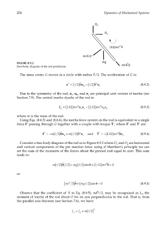
FIGURE 8.9.2 mg θ 2
Free-body diagram of the rod pendulum. m /2
The mass center G moves in a circle with radius /2. The acceleration of G is:
a = ( ) 2 θ ˙˙ n −( ) 2 θ 2 ˙ n r (8.9.2)
G
l
l
θ
Due to the symmetry of the rod, n , n , and n are principal unit vectors of inertia (see
θ
r
z
Section 7.9). The central inertia dyadic of the rod is:
2
l
I = (112 m ) l 2 n n +(1 12 ) m n n (8.9.3)
G r r θθ
where m is the mass of the rod.
Using Eqs. (8.6.5) and (8.6.6), the inertia force system on the rod is equivalent to a single
*
*
force F passing through G together with a couple with torque T , where F and T are:
*
*
˙˙
F =− ( ) 2 θ n + ( ) 2 θ ˙ 2 n and T =−(1 12 )ml θ n z (8.9.4)
˙˙
2
*
*
m l
m l
θ
r
Consider a free-body diagram of the rod as in Figure 8.9.2 where O and O are horizontal
x
y
and vertical components of the pin reaction force: using d’Alembert’s principle we can
set the sum of the moments of the forces about the pinned end equal to zero. This sum
leads to:
(
(
m l 2) ( θ l 2) + mg l 2)sinθ +( 1 12) ml θ = 0
2˙˙
˙˙
or
( ml 3) +( mgl 2)sinθ = 0 (8.9.5)
θ
˙˙
2
Observe that the coefficient of in Eq. (8.9.5), m /3, may be recognized as I , theθ 2 O
˙˙
moment of inertia of the rod about O for an axis perpendicular to the rod. That is, from
the parallel axis theorem (see Section 7.6), we have:
I = I + m( ) 2 2
l
O G