
Page 277 - Dynamics of Mechanical Systems
P. 277
0593_C08_fm Page 258 Monday, May 6, 2002 2:45 PM
258 Dynamics of Mechanical Systems
8.10 Double-Rod Pendulum
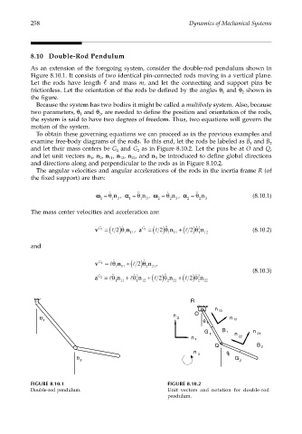
As an extension of the foregoing system, consider the double-rod pendulum shown in
Figure 8.10.1. It consists of two identical pin-connected rods moving in a vertical plane.
Let the rods have length and mass m, and let the connecting and support pins be
frictionless. Let the orientation of the rods be defined by the angles θ and θ shown in
1 2
the figure.
Because the system has two bodies it might be called a multibody system. Also, because
two parameters, θ and θ , are needed to define the position and orientation of the rods,
1 2
the system is said to have two degrees of freedom. Thus, two equations will govern the
motion of the system.
To obtain these governing equations we can proceed as in the previous examples and
examine free-body diagrams of the rods. To this end, let the rods be labeled as B and B
1 2
and let their mass centers be G and G as in Figure 8.10.2. Let the pins be at O and Q,
1 2
and let unit vectors n , n , n , n , n , and n be introduced to define global directions
1 2 11 12 22 3
and directions along and perpendicular to the rods as in Figure 8.10.2.
The angular velocities and angular accelerations of the rods in the inertia frame R (of
the fixed support) are then:
˙˙
˙
˙˙
˙
ωω = θ n , αα = θ n , ωω = θ n , αα = θ n (8.10.1)
1 1 3 1 1 3 2 2 3 2 2 3
The mass center velocities and acceleration are:
v G 1 = (l 2)θ ˙ n , a G 1 = (l 2)θ ˙˙ n +(l 2)θ 2 ˙ n (8.10.2)
1 11 1 11 1 12
and
v G 2 = lθ ˙ n +(l 2)θ ˙ n ,
111 2 21
(8.10.3)
˙˙
˙˙
a G 2 = lθ n + lθ 2 ˙ n +(l 2)θ n +(l 2)θ 2 ˙ n
111 1 12 2 21 2 22
R
n 12
θ n 2 O n 11
1
θ 1
G B 1 n
1 n 21
22
n 1
Q B 2
n θ 2
θ 2 3 G 2
FIGURE 8.10.1 FIGURE 8.10.2
Double-rod pendulum. Unit vectors and notation for double-rod
pendulum.