
Page 41 - Dynamics of Mechanical Systems
P. 41
0593_C02_fm Page 22 Monday, May 6, 2002 1:46 PM
22 Dynamics of Mechanical Systems
Z Z
B
n
z
n P(x,y,z)
z
C
C A
R
Y O
n Y
n x y
n
y
X n x
X
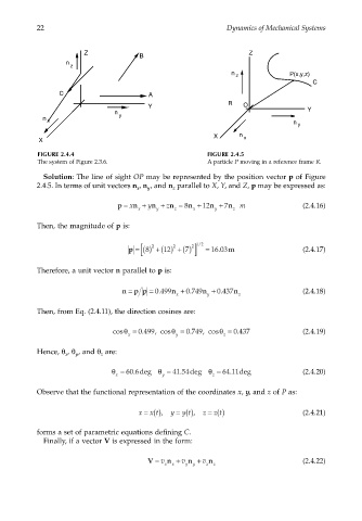
FIGURE 2.4.4 FIGURE 2.4.5
The system of Figure 2.3.6. A particle P moving in a reference frame R.
Solution: The line of sight OP may be represented by the position vector p of Figure
2.4.5. In terms of unit vectors n , n , and n parallel to X, Y, and Z, p may be expressed as:
y
x
z
p = x n + y n + z n = 8 n + 12 n + 7 n m (2.4.16)
x y z x y z
Then, the magnitude of p is:
[ 2 2 2 ] 12
/
12
8
.
p = () +() +() 7 = 16 03m (2.4.17)
Therefore, a unit vector n parallel to p is:
n = p p = 0 499 n + 0 749 n + 0 437 n (2.4.18)
.
.
.
x y z
Then, from Eq. (2.4.11), the direction cosines are:
cosθ = 0 .499 , cosθ = 0 .749 , cosθ = 0 .437 (2.4.19)
x y z
Hence, θ , θ , and θ are:
x
y
z
.
θ = 60 6deg θ = 4154deg θ = 6411deg (2.4.20)
.
.
x y z
Observe that the functional representation of the coordinates x, y, and z of P as:
x = (), y = (), z = () (2.4.21)
z t
y t
x t
forms a set of parametric equations defining C.
Finally, if a vector V is expressed in the form:
V = v n + v n + v n (2.4.22)
x x y y z z