
Page 14 - Electric Drives and Electromechanical Systems
P. 14
6 Electric Drives and Electromechanical Systems
concern during the roughing cut (that is, when the cutting depth is at its maximum),
when it is essential to ensure that the drive system will produce sufficient power for the
operation. The main parameters are the tangential cutting force, F c , and the cutting
speed, V c . The cutting speed is defined as the relative velocity between the tool and the
1
surface of the workpiece (m min ). In the turning operation, the cutting speed is
1
directly related to the spindle speed, N (rev min ), by;
V c ¼ dpN (1.1)
where, d, is the diameter of the cut being made. The tangential force experienced by the
cutter can be determined from knowledge of the process, in particular the specific
cutting force, K, is determined by the manufacturer of the cutting tool, which is a
function of the materials involved, and other parameters, including the cutting angles
and the tools design. Based on the tangential forces, the power requirement of the
spindle drive can be estimated using;
V c F c
Power ¼ (1.2)
60
In modern CNC lathes, the feed rate and the depth of the cut will be individually
controlled using separate motion-control systems. While the forces will be considerably
smaller than those experienced by the spindle, they still must be quantified during any
design process. The locations of the forces at the point of cutting also shown in Fig. 1.2;
their magnitudes are, in practice, a function of the approach and cutting angles of the
tool. Their determination of these magnitudes is outside the scope of this book, but it
can be found in texts relating to machining processes or manufacturers’ data sheets.
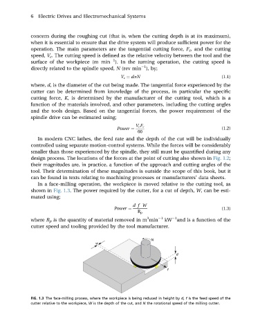
In a face-milling operation, the workpiece is moved relative to the cutting tool, as
shown in Fig. 1.3. The power required by the cutter, for a cut of depth, W, can be esti-
mated using;
df W
Power ¼ (1.3)
R p
3
1
where R p is the quantity of material removed in m min 1 kW and is a function of the
cutter speed and tooling provided by the tool manufacturer.
FIG. 1.3 The face-milling process, where the workpiece is being reduced in height by d, f is the feed speed of the
cutter relative to the workpiece, W is the depth of the cut, and N the rotational speed of the milling cutter.