
Page 70 - Electric Drives and Electromechanical Systems
P. 70
Chapter 2 Analysing a drive system 63
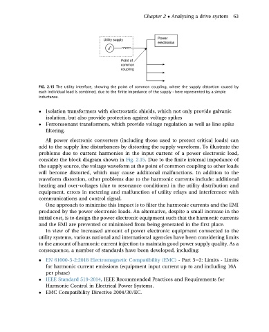
FIG. 2.15 The utility interface, showing the point of common coupling, where the supply distortion caused by
each individual load is combined, due to the finite impedance of the supply - here represented by a simple
inductance.
Isolation transformers with electrostatic shields, which not only provide galvanic
isolation, but also provide protection against voltage spikes
Ferroresonant transformers, which provide voltage regulation as well as line spike
filtering.
All power electronic converters (including those used to protect critical loads) can
add to the supply line disturbances by distorting the supply waveform. To illustrate the
problems due to current harmonies in the input current of a power electronic load,
consider the block diagram shown in Fig. 2.15. Due to the finite internal impedance of
the supply source, the voltage waveform at the point of common coupling to other loads
will become distorted, which may cause additional malfunctions. In addition to the
waveform distortion, other problems due to the harmonic currents include: additional
heating and over-voltages (due to resonance conditions) in the utility distribution and
equipment, errors in metering and malfunction of utility relays and interference with
communications and control signal.
One approach to minimise this impact is to filter the harmonic currents and the EMI
produced by the power electronic loads. An alternative, despite a small increase in the
initial cost, is to design the power electronic equipment such that the harmonic currents
and the EMI are prevented or minimised from being generated in the first place.
In view of the increased amount of power electronic equipment connected to the
utility systems, various national and international agencies have been considering limits
to the amount of harmonic current injection to maintain good power supply quality. As a
consequence, a number of standards have been developed, including:
EN 61000-3-2:2018 Electromagnetic Compatibility (EMC) - Part 3e2: Limits - Limits
for harmonic current emissions (equipment input current up to and including 16A
per phase)
IEEE Standard 519-2014, IEEE Recommended Practices and Requirements for
Harmonic Control in Electrical Power Systems.
EMC Compatibility Directive 2004/30/EC.