
Page 101 - Electric Machinery Fundamentals
P. 101
TRANSFORMERS 77
transformers. This simple example dramatically illustrates the advantages of
using higher-voltage transmission lines as well as the extreme importance of
transformers in modern power systems.
Real power systems generate electric power at voltages in the range of 4 to
30 kV They then use step-up transformers to raise the voltage to a much higher level
(say 500 kV) for transmission over long distances, and step-down transformers to re-
duce the voltage to a reasonable level for distribution and final use. As we have seen
in Example 2.1, this can greatly decrease transmission losses in the power system.
2.4 THEORY OF OPERATION OF REAL
SINGLE· PHASE TRANSFORMERS
The ideal transformers described in Section 2.3 can of course never actually be
made. What can be produced are real transformers~two or more coils of wire
physically wrapped around a ferromagnetic core. The characteristics of a real
f transformer approximate the characteristics of an ideal transformer, but only to a
degree. This section deals with the behavior of real transformers.
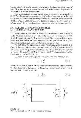
To understand the operation of a real transformer, refer to Figure 2- 8.
Figure 2- 8 shows a transformer consisting of two coils of wire wrapped around a
transformer core. The primary of the transformer is connected to an ac power
source, and the secondary winding is open-circuited. The hysteresis curve of the
transformer is shown in Figure 2-9.
The basis of transformer operation can be derived from Faraday's law:
dA
eind = dt (1-41)
where A is the flux linkage in the coi1 across which the voltage is being induced.
The flux linkage).. is the sum of the flux passing through each turn in the coil
added over all the turns of the coil:
N
A = '2:,</>; 0 -42)
j= 1
i/,(/)
+
l' Ns ) "s (I)
vp(t)
FIGURE 2-8
Sketch of a real transformer with no load attached to its secondary.