
Page 102 - Electric Machinery Fundamentals
P. 102
78 ELECTRIC MACHINERY FUNDAMENTALS
0/ Flux
~--------j++-------- Magnetomotive force
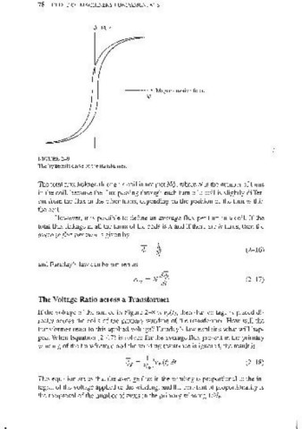
FIGURE 2-9
The hysteresis curve of the transformer.
The total flux linkage through a coil is not just N</>, where N is the number of turns
in the coil, because the flux passing through each turn of a coil is slightly differ-
ent from the flux in the other turns, depending on the position of the tum within
the coiL
However, it is possible to define an average flux per turn in a coil. If the
total flux linkage in all the turns of the coils is A and if there are N turns, then the
average flux per turn is given by
- A
</>= ~ (2-1 6)
N
and Faraday's law can be written as
_ 4</J.
eind - N dt (2-17)
The Voltage Ratio across a Transformer
If the voltage of the source in Figure 2-8 is vp(t), then that voltage is placed di-
rectly across the coils of the primm"y winding of the transformer. How will the
transformer react to this applied voltage? Faraday's law explains what will hap-
pen. When Equation (2- 17) is solved for the average flux present in the primary
winding of the transformer, and the winding resistance is ignored, the result is
- 1 f (2-18)
</>P = IV vpCt) dt
p
This equation states that the average flux in the winding is proportional to the in-
tegral of the voltage applied to the winding, and the constant of proportionality is
the reciprocal of the number of turns in the primary winding liN p.