
Page 38 - Electric Machinery Fundamentals
P. 38
14 ELECTRIC MACHINERY FUNDAMENTALS
j
N
t
S
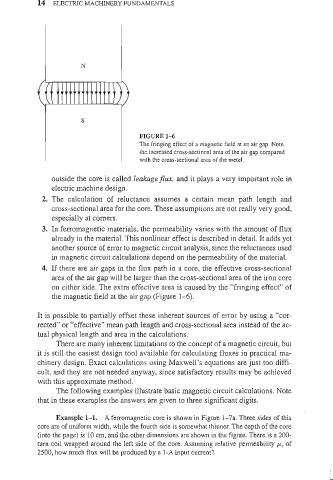
FIGURE 1- 6
The fringing effect of a magnetic field at an air gap. Note
the increased cross-sectional area of the air gap compared
with the cross-sectional area of the metal.
outside the core is called leakage flux, and it plays a very important role in
electric machine design.
2. The calculation of reluctance assumes a certain mean path length and
cross-sectional area for the core. These assumptions are not really very good,
especially at corners.
3. In ferromagnetic materials, the permeability varies with the amount of flux
already in the material. This nonlinear effect is described in detail. It adds yet
another source of error to magnetic circuit analysis, since the reluctances used
in magnetic circuit calculations depend on the permeability of the material.
4. If there are air gaps in the flux path in a core, the effective cross-sectional
area of the air gap will be larger than the cross-sectional area of the iron core
on either side. The extra effective area is caused by the "fri nging effect" of
the magnetic field at the air gap (Figure 1- 6).
It is possible to partially offset these inherent sources of error by using a "cor-
rected" or "effective" mean path length and cross-sectional area instead of the ac-
tual physical length and area in the calculations.
There are many inherent limitations to the concept of a magnetic circuit, but
it is still the easiest design tool available for calculating fluxes in practical ma-
chinery design. Exact calculations using Maxwell's equations are just too diffi-
cult, and they are not needed anyway, since satisfactory results may be achieved
with this approximate method.
The following examples illustrate basic magnetic circuit calculations. Note
that in these examples the answers are given to three significant digits.
Example 1- 1. A ferromagnetic core is shown in Figure 1-7a. Three sides of this
eore are of uniform width, while the fourth side is somewhat thinner. The depth of the core
(into the page) is 10 em, and the other dimensions are shown in the figure. There is a 200-
turn coil wrapped around the left side of the core. Assuming relative permeability J.l..r of
2500, how much flux will be produced by a I-A input current?