
Page 35 - Electric Machinery Fundamentals
P. 35
INTRODUCTION TO MACHINERY PRINCIPLES 11
- .p-
v + R + ttJ= Ni
1= !!.-
R
(0) (b)
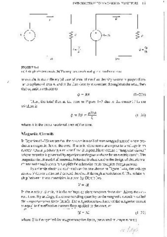
FIGURE 1-4
(a) A simple electric circuit. (b) The magnetic circuit analog to a transformer core.
where dA is the differential unit of area. If the flux density vector is perpendicu-
lar to a plane of area A, and if the flux density is constant throughout the area, then
this equation reduces to
(1- 2Sb)
'" = BA
Thus, the total flux in the core in Figure 1-3 due to the current i in the
winding is
'" = BA = f.LNiA (1- 26)
(
where A is the cross-sectional area of the core.
Magnetic Circuits
In Equation (1- 26) we see that the current in a coil of wire wrapped around a core pro-
duces a magnetic flux in the core. This is in some sense analogous to a voltage in an
electric circuit producing a current flow. It is possible to define a "magnetic circuit"
whose behavior is governed by equations analogous to those for an electric circuit. The
magnetic circuit mooel of magnetic behavior is often used in the design of electric ma-
chines and transformers to simplify the othelwise quite complex design process.
In a simple electric circuit such as the one shown in Figure 1-4a, the voltage
source V dl1ves a current I around the circuit through a resistance R. The relation-
ship between these quantities is given by Ohm's law:
V = IR
In the electric circuit, it is the voltage or electromotive force that drives the cur-
rent flow. By analogy, the corresponding quantity in the magnetic circuit is called
( the magnetonwtive force (mmf) . The magnetomotive force of the magnetic circuit
is equal to the effective current flow applied to the core, or
~ --
'ti'=Ni (1-27)
where g is the symbol for magnetomotive force, measured in ampere-turns.