
Page 56 - Electric Machinery Fundamentals
P. 56
32 ELECTRIC MACHINERY FUNDAM EN'IALS
/ /
Require d direction of i
i
+ --..,
"-
--.., N:::: 100 turns
--..,
--..,
Opposing ¢--:
•
L=¢ /
¢ :::: 0.05 sin 377t Wb
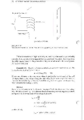
FIGURE 1- 15
The core of Example 1-6. Determination of the voltage polarity at the terminals is shown.
Either laminations or high-resistivity materials can be used to control eddy
currents, In many cases, both approaches are combined, Together, they can reduce
the eddy cun'ent losses to the point where they are much smaller than the hystere-
sis losses in the core.
Example 1-6. Figure 1-15 shows a coil of wire wrapped around an iron core, The
flux in the core is given by the equation
'" ~ 0.05 sin 3771 Wb
If there are [00 turns on the core, what voltage is produced at the terminals of the coil?
Of what polarity is the voltage during the time when flux is increasing in the reference
direction shown in the figure? Assume that all the magnetic flux stays within the core (i.e.,
assume that the flux leakage is zero).
Solution
By the same reasoning as in the discussion on pages 29-30, the direction of the voltage
while the flux is increasing in the reference direction must be positive to negative, as shown
in Figure 1-15. The magnilllde of the voltage is given by
~ (100 turns) 1r (0.05 sin 3771)
~ 1885 cos 3771
or alternati vely,
e;nd = 1885 sin(377t + 90°) V