
Page 102 - Electrical Equipment Handbook _ Troubleshooting and Maintenance
P. 102
AC MACHINE FUNDAMENTALS
AC MACHINE FUNDAMENTALS 5.3
B B 0°
M
aa'
B 0.5B 120°
bb' M
B 0.5B 240°
cc'
M
The resulting net magnetic field is
B B 0° ( 0.5) B 120° ( 0.5) B 240°
M
M
M
net
1.5B 0°
M
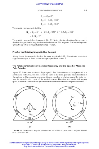
The resulting magnetic flux is shown in Fig. 5.2. Notice that the direction of the magnetic
flux has changed, but its magnitude remained constant. The magnetic flux is rotating coun-
terclockwise while its magnitude remained constant.
Proof of the Rotating Magnetic Flux Concept
At any time t, the magnetic flux has the same magnitude 1.5B . It continues to rotate at
M
angular velocity . A proof of this concept is presented in Ref. 1.
The Relationship between Electrical Frequency and the Speed of Magnetic
Field Rotation
Figure 5.3 illustrates that the rotating magnetic field in the stator can be represented as a
north and a south pole. The flux leaves the stator at the north pole and enters the stator at
the south pole. The magnetic poles complete one complete revolution around the stator sur-
face for each electrical cycle of the applied current. Therefore, the mechanical angular
speed of rotation in revolutions per second is equal to the electrical frequency in hertz:
FIGURE 5.2 (a) The vector magnetic field in a stator at time t 0°. (b) The vector magnetic field in a
stator at time t 90°.
Downloaded from Digital Engineering Library @ McGraw-Hill (www.digitalengineeringlibrary.com)
Copyright © 2004 The McGraw-Hill Companies. All rights reserved.
Any use is subject to the Terms of Use as given at the website.