
Page 103 - Electrical Equipment Handbook _ Troubleshooting and Maintenance
P. 103
AC MACHINE FUNDAMENTALS
5.4 CHAPTER FIVE
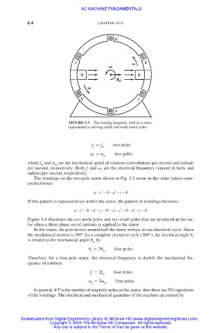
FIGURE 5.3 The rotating magnetic field in a stator
represented as moving north and south stator poles.
f f m two poles
e
two poles
e m
where f and are the mechanical speed of rotation in revolutions per second and radians
m
m
per second, respectively. Both f and are the electrical frequency (speed) in hertz and
e
e
radians per second, respectively.
The windings on the two-pole stator shown in Fig. 5.1 occur in the order (taken coun-
terclockwise)
a c' b a' c b
If this pattern is repeated twice within the stator, the pattern of windings becomes
a c' b a' c b' a c' b a' c b'
Figure 5.4 illustrates the two north poles and two south poles that are produced in the sta-
tor when a three-phase set of currents is applied to the stator.
In this stator, the pole moves around half the stator surface in one electrical cycle. Since
the mechanical motion is 180° for a complete electrical cycle (360°), the electrical angle e
is related to the mechanical angle by
m
2 four poles
e m
Therefore, for a four-pole stator, the electrical frequency is double the mechanical fre-
quency of rotation:
f 2f four poles
e m
2 m four poles
e
In general, if P is the number of magnetic poles on the stator, then there are P/2 repetitions
of the windings. The electrical and mechanical quantities of the machine are related by
Downloaded from Digital Engineering Library @ McGraw-Hill (www.digitalengineeringlibrary.com)
Copyright © 2004 The McGraw-Hill Companies. All rights reserved.
Any use is subject to the Terms of Use as given at the website.