
Page 234 - Electrical Equipment Handbook _ Troubleshooting and Maintenance
P. 234
SYNCHRONOUS MACHINES
SYNCHRONOUS MACHINES 11.9
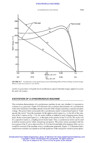
FIGURE 11.7 Synchronous motor speed-torque curves illustrating effect of field winding on motor torque.
Effect of rotor bar material is also shown.
(motor or generator) will pull out of synchronous speed when the torque applied exceeds
the pull-out torque.
EXCITATION OF A SYNCHRONOUS MACHINE
The excitation characteristics of a synchronous machine do not vary whether it is operated as
a motor or as a generator. Figure 11.8 illustrates the excitation characteristics of a synchronous
motor (the variations of armature current versus the field voltage) assuming a constant armature
voltage. The power factor associated with a synchronous motor is determined based on “look-
ing into the motor” from the terminals. In the underexcited region (i.e., to the left of the min-
ima of the V curves in Fig. 11.8), the motor will be an inductive load (a lagging power factor
load). In the overexcited region (i.e., to the right of the minima of the V curves), the motor will
be a capacitive load (i.e., a leading power factor load). Thus, a synchronous motor can be used
to deliver reactive power while consuming real power. The power factor associated with the
two regions of the V curves shown in Fig. 11.8 (to the left and right of the minima of the curves)
would be reversed if the machine were a synchronous generator. Figure 11.9 illustrates that a
synchronous machine can operate in all four quadrants of the real power–reactive power plane.
Downloaded from Digital Engineering Library @ McGraw-Hill (www.digitalengineeringlibrary.com)
Copyright © 2004 The McGraw-Hill Companies. All rights reserved.
Any use is subject to the Terms of Use as given at the website.