
Page 101 - Electrical Installation in Hazardous Area
P. 101
Area classification for gases, vapours and mists 77
hazardous areas produced by this method would not be acceptable. This
gives rise to the following area classifications. The interior of the separator
will be Zone 0, but this Zone will not extend beyond the extremities of the
separator due to the oils it contains being of low volatility. It would be
unwise to use an oil/water separator of this type if the oils were of high
volatility and some other approach should be used in those circumstances.
Zone 1 occurs in cases where the separator contains oils of a higher volatility
than normally and, due to wind action, a hazardous area will exist outside
the oil/water separator. In these cases the mix of volatility should be such
as to permit the use of the 50 per cent column of Table 3.7, using the area of
the separator as the pool size. In cases where a significant number of the oils
on the plant - which may be fed to the separator - are of high volatility the
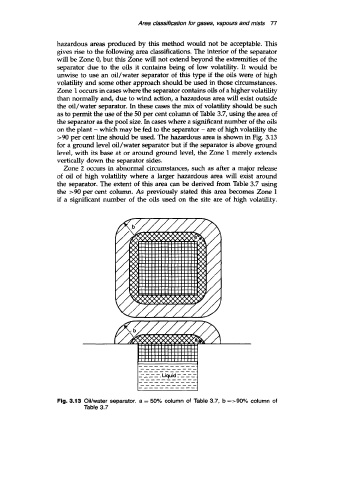
>90 per cent line should be used. The hazardous area is shown in Fig. 3.13
for a ground level oil/water separator but if the separator is above ground
level, with its base at or around ground level, the Zone 1 merely extends
vertically down the separator sides.
Zone 2 occurs in abnormal circumstances, such as after a major release
of oil of high volatility where a larger hazardous area will exist around
the separator. The extent of this area can be derived from Table 3.7 using
the >90 per cent column. As previously stated this area becomes Zone 1
if a significant number of the oils used on the site are of high volatility.
Fig. 3.13 OiVwater separator. a = 50% column of Table 3.7, b =>go% column of
Table 3.7