
Page 106 - Electrical Installation in Hazardous Area
P. 106
82 Electrical installations in hazardous areas
spillages into the tundish will be necessary. If these techniques are used
the release of flammable material into the atmosphere surrounding the
sampling point in normal operation will be minimal and no significant
Zone 1 will exist. There will, however, remain the possibility of si@-
cant release in abnormal operation due to such things as failure of the
sampling valve which will release too much liquid for the tundish to deal
with, or blockage of the tundish itself. In both of these cases there will
be significant leakage of flammable liquid and possible splashing around
the sampling point. This situation will produce a small Zone 2 around the
sampling point and a pool below it which will grow until it is contained
either physically or by the evaporation rate. It will then create a hazardous
area as defined in Table 3.7. The result of this is given in Fig. 3.15 and is as
follows.
There are no Zones 0 and 1.
Zone 2 consists of a sphere of 1 m around the sampling point and a pool
with surrounding hazardous area below it.
Where the flammable material is not toxic simpler arrangements are
possible but not recommended as they will probably create larger hazardous
areas, the justification for which is doubtful in view of the ease with which
the above arrangements can be used. Details of toxicity for more usual
materials is given in HSE Guidance Note EH 40.6
Sampling gases and vapours
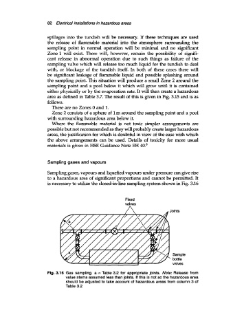
Sampling gases, vapours and liquefied vapours under pressure can give rise
to a hazardous area of significant proportions and cannot be permitted. It
is necessary to utilize the closed-in-line sampling system shown in Fig. 3.16
Fixed
valves
Fig. 3.16 Gas sampling. a = Table 3.2 for appropriate joints. Note: Release from
value stems assumed less than joints. If this is not so the hazardous area
should be adjusted to take account of hazardous areas from column 3 of
Table 3.2