
Page 107 - Electrical Installation in Hazardous Area
P. 107
Area classification for gases, vapours and mists 83
and, in some cases, even to allow for the evacuation of the spaces between
the sample bottle and fixed valves before disconnection of the sample bottle.
This is likely only in the case of liquefied gases as, otherwise, the amount
of flammable material stored in this interspace will be small if the system is
properly designed. Again the objective is to effectively eliminate any Zone 1
so that only in abnormal operation will a hazardous area be present. These
abnormal situations will include valve seal failure, pipe-joint failure and
incorrect connection by personnel, the latter of which would be expected
to be quickly corrected as the sampling personnel would be present. The
hazardous area would, therefore, be most likely from pipe-joint or valve
failure, both of which are dealt with in sections 3.5.1 and 3.5.2 and in
Table 3.2. The result of this is as follows.
There are no Zones 0 and 1
Zone 2 consists of an area in accordance with line 3 of Table 3.2 around
the valve stem and an area in accordance with the appropriate column of
Table 3.2 around each joint, as shown in Fig. 3.16.
Wall
Wall
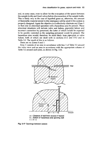
a = Distance of wall from source of hazard
b = Extent of hazardous area ignoring wall
c = b-a
Fig. 3.17 Openings between spaces