
Page 83 - Electrical Safety of Low Voltage Systems
P. 83
66 Chapter Four
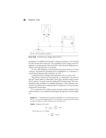
FIGURE 4.26 Standard touch voltage measurement.
parameter to establish the hazard in electrical systems, even though
it is the easiest one to measure. The capability of the voltage source to
impress a current greater than the body value deemed dangerous is,
instead, the right quantity to consider.
To solve this dilemma, and normalize the measurement of touch
voltages, international standards have established, as a reference, a
conventional human body resistance of 1 k .
A standard touch voltage measurement is shown in Fig. 4.26.
The person’s resistance to ground R BG is “simulated” by a pair of
2
200 cm metal plates as electrodes. Each plate should weigh at least
250 N and be 1 m apart from the faulted ECP being tested. The stan-
dardized body resistance is modeled through a 1-k resistance con-
nected in parallel to the voltmeter leads. The person is conservatively
supposed to be shoeless.
If we measured the voltage across an open circuit, instead of the
1-k resistance, we would be measuring the perspective touch voltage
V ST .
Example 4.1 A hemispherical electrode is embedded in a soil with resistivity of
200 · m (e.g., poorly graded gravel). Calculate the size of the electrode’s radius
in order to achieve an earth resistance not exceeding 10 .
Solution Equation (4.2) yields:
200
R G = = ≤ 10
2 r 0 2 r 0
By solving for r 0 , we obtain
200
r 0 ≥ = 3.18 m
20