
Page 37 - Electrical Properties of Materials
P. 37
20 The electron as a particle
Here df is the measurement bandwidth, sometimes written as B. An analogous
expression exists for noise generated as a shunt current. At room temperature
√ 2 √ √
(300 K) this result implies that <V n > = 0.129 R nV per Hz. For ex-
√ 2
ample, for a 1 M resistor and a 10 kHz bandwidth, <V n > = 12.9 μV.
That gives you an idea.
The main point is that there is no getting away from noise. All electrical
sources have an output resistance. Consequently, while they may generate a
signal (which we want) they will also generate noise (which we don’t want).
As a result, the perfect signal is an idealization, although a convenient one.
More realistic signals must be described in terms of a signal-to-noise ratio or
SNR, defined as the signal power divided by the noise power. For a sinusoidal
2
2
signal with r.m.s. voltage V S , the SNR is clearly V /<V >. If the SNR is too
S n
low (which occurs at about unity), it will be difficult to distinguish the signal
from noise. As a result, SNR will in the end set a limit to the signals that can
be measured and the distances over which they can be transmitted. There is not
much we can do to improve the situation. There is no way of subtracting away
the noise, since it is generated randomly. Additional circuitry will make matters
worse, because it will contain some conductive elements. We can illustrate this
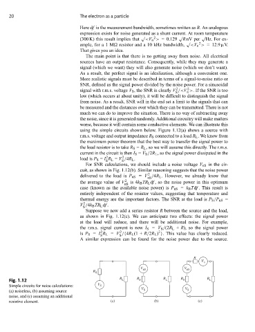
using the simple circuits shown below. Figure 1.12(a) shows a source with
r.m.s. voltage and output impedance R S connected to a load R L . We know from
the maximum power theorem that the best way to transfer the signal power to
the load resistor is to take R S = R L , so we will assume this directly. The r.m.s.
current in the circuit is then I S = V S /2R L , so the signal power dissipated in the
2
2
load is P S = I R L = V /4R L .
S S
For SNR calculations, we should include a noise voltage V nS in the cir-
cuit, as shown in Fig. 1.12(b). Similar reasoning suggests that the noise power
2
delivered to the load is P nS = V /4R L . However, we already know that
nS
the average value of V 2 is 4k B TR L df , so the noise power in this optimum
nS
case (known as the available noise power) is P nS = k B Tdf . This result is
entirely independent of the resistor values, suggesting that temperature and
thermal energy are the important factors. The SNR at the load is P S /P nS =
2
V /4k B TR L df .
S
Suppose we now add a series resistor R between the source and the load,
as shown in Fig. 1.12(c). We can anticipate two effects: the signal power
at the load will reduce, and there will be additional noise. For example,
the r.m.s. signal current is now I S = V S /(2R L + R), so the signal power
2
2
2
is P S = I R L = V /{4R L (1 + R/2R L ) }. This value has clearly reduced.
S S
A similar expression can be found for the noise power due to the source.
R
V n
V V
R S nS nS
Fig. 1.12 R L R S R L R S R L
Simple circuits for noise calculations: V S
V S V S
(a) noiseless, (b) assuming source
noise, and (c) assuming an additional
resistive element. (a) (b) (c)