
Page 285 - Electromagnetics
P. 285
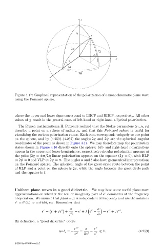
Figure 4.17: Graphical representation of the polarization of a monochromatic plane wave
                                       e
                        using the Poincar´ sphere.


                        where the upper and lower signs correspond to LHCP and RHCP, respectively. All other
                        values of χ result in the general cases of left-hand or right-hand elliptical polarization.
                                                           e
                          The French mathematician H. Poincar´ realized that the Stokes parameters (s 1 , s 2 , s 3 )
                        describe a point on a sphere of radius s 0 , and that this Poincar´e sphere is useful for
                        visualizing the various polarization states. Each state corresponds uniquelyto one point
                        on the sphere, and by(4.250)–(4.252) the angles 2χ and 2ψ are the spherical angular
                        coordinates of the point as shown in Figure 4.17. We maytherefore map the polarization
                        states shown in Figure 4.16 directlyonto the sphere: left- and right-hand polarizations
                        appear in the upper and lower hemispheres, respectively; circular polarization appears at
                        the poles (2χ =±π/2); linear polarization appears on the equator (2χ = 0), with HLP
                        at 2ψ = 0 and VLP at 2ψ = π. The angles α and δ also have geometrical interpretations
                        on the Poincar´ sphere. The spherical angle of the great-circle route between the point
                                     e
                        of HLP and a point on the sphere is 2α, while the angle between the great-circle path
                        and the equator is δ.


                        Uniform plane waves in a good dielectric.   We maybase some useful plane-wave
                                                                           c
                        approximations on whether the real or imaginarypart of ˜  dominates at the frequency
                        of operation. We assume that ˜µ(ω) = µ is independent of frequencyand use the notation
                         c
                             c
                          = ˜  ( ˇω), σ = ˜σ( ˇω), etc. Remember that
                                                       σ               σ
                                        c


                                                                                   c

                                                                             c
                                         =   + j       +  =   + j   −     =   + j  .
                                                       j ˇω            ˇ ω
                        Bydefinition, a “good dielectric” obeys
                                                            c    σ
                                                 tan δ c =−  =     −      1.                  (4.253)
                                                             c   ˇ ω
                        © 2001 by CRC Press LLC