Page 353 - Electromagnetics
P. 353

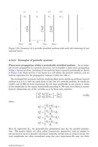
Figure 4.34: Geometry of a periodic stratified medium with each cell consisting of two
                        material layers.


                        4.14.2   Examples of periodic systems

                        Plane-wave propagation within a periodically stratified medium.    As an exam-
                        ple of wave propagation in a periodic structure, let us consider a plane wave propagating
                        within a layered medium consisting of two material layers repeated periodically as shown
                        in Figure 4.34. Each section of two layers is a cell within the periodic medium, and we
                        seek an expression for the propagation constant within the cells, κ.
                          We developed the necessary tools for studying plane waves within an arbitrary layered
                        medium in § 4.11.5, and can apply them to the case of a periodic medium. In equations
                        (4.305) and (4.306) we have expressions for the wave amplitudes in any region in terms
                        of the amplitudes in the region immediately preceding it. We may write these in matrix
                        form by eliminating one of the variables a n or b n from each equation:

                                                     (n)  (n)
                                                   T   T
                                                    11  12    a n+1  =  a n                   (4.423)
                                                   T  (n)  T  (n)  b n+1  b n
                                                    21  22
                        where
                                                                     ˜ −1
                                                    T  (n)  =  1 Z n + Z n−1  P  ,
                                                     11              n
                                                          2    Z n
                                                     (n)  1 Z n − Z n−1
                                                                     ˜
                                                    T  =            P n ,
                                                     12
                                                          2    Z n
                                                     (n)  1 Z n − Z n−1
                                                                     ˜ −1
                                                    T  =            P   ,
                                                     21              n
                                                          2    Z n
                                                                     ˜
                                                    T  (n)  =  1 Z n + Z n−1  P n .
                                                     22
                                                          2    Z n
                        Here Z n represents Z n⊥ for perpendicular polarization and Z n  for parallel polariza-
                        tion. The matrix entries are often called transmission parameters, and are similar to
                        the parameters used to describe microwave networks, except that in network theory the
                        wave amplitudes are often normalized using the wave impedances.We may use these

                        © 2001 by CRC Press LLC
   348   349   350   351   352   353   354   355   356   357   358