
Page 203 - Electromechanical Devices and Components Illustrated Sourcebook
P. 203
Chapter 9 Connectors 165
used to mount the strip. Spacers are fitted to the studs and
thumb nuts are used to secure the protective plate. The plate
can also serve to identify the function of the device by print-
ing a label on the top as shown.
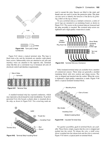
To use a terminal strip as a multipin connector, a series of
screw lugs are mounted to an insulating board, as shown in
Figure 9-63. The screws in the terminal strip are loosened and
the plug assembly is inserted. The terminal strip screws are
tightened and a high-quality connection is made.
Lock
Solder
Brass Rivets
Terminals
Insulating
Plug Assembly
Unisex Board
Screw Lugs
Figure 9-60 Turn-Lock or Hook
Connectors
Terminal
Strip
Figure 9-61 shows a typical terminal strip. The base is
black bake-a-lite and the terminals are number eight plated
brass screws. Subassembly wires are attached to one side and
interface wires are attached to the opposite side. Terminal Figure 9-63 Terminal Strip as a Connector
strips like this are a convenient way to terminate all sorts of
electrical control and interface requirements.
Fully insulated terminal strips are available from a number
of commercial sources. These strips are generally a molded
Mount Holes
insulating block with wire sockets and clamp screws. The
Terminals
wire is stripped and inserted into the socket. When the screw
is tightened a high-quality connection is made. Figure 9-64
shows a typical insulated terminal block.
Mounting Holes
Figure 9-61 Terminal Strip
Clamp Screws
A standard terminal strip has exposed conductors, which
may represent a shock hazard in some installations. To protect
personnel from this hazard, a plastic plate is mounted above
the strip, as shown in Figure 9-62. Two extra-long studs are
Wire Socket
Label
Insulating Collar
Molded Insulating Block
Thumb Nut
Danger
High Voltage
Insulating Panel Figure 9-64 Insulated Terminal Strip
Stud For quicker assemblies, push-in terminal blocks are avail-
Terminal Strip
Spacer able. These blocks simply require that the wire is stripped and
pushed into the socket. To release the wire, a small screw
driver is pushed into the release hole and the wire is removed.
Figure 9-62 Terminal Strip Insulating Panel Figure 9-65 shows a typical push-in terminal block.