
Page 42 - Electromechanical Devices and Components Illustrated Sourcebook
P. 42
4 Electromechanical Devices & Components Illustrated Sourcebook
(current), and by reducing the load on the paddle wheel you
reduce resistance to flow (ohms).
It can be seen that by increasing the pressure on the system E
E = volts
(voltage), you increase flow through the pipe and the paddle I = amperes
wheel goes faster. By increasing the pipe size (current), the R = ohms
flow can be higher and the paddle wheel will go faster. By I R
decreasing the load on the paddle wheel (ohms), its speed will
increase. In this manner you can see how the three parameters (X)
are interrelated.
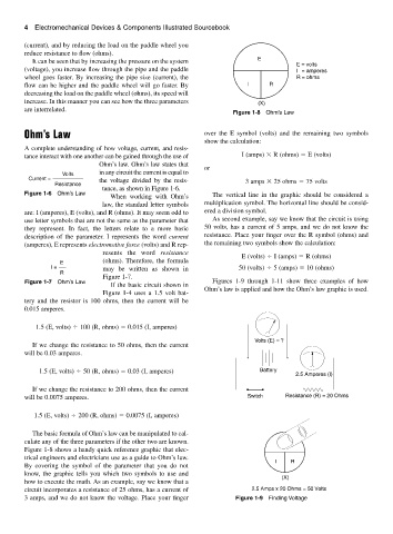
Figure 1-8 Ohm’s Law
Ohm’s Law over the E symbol (volts) and the remaining two symbols
show the calculation:
A complete understanding of how voltage, current, and resis-
tance interact with one another can be gained through the use of I (amps) R (ohms) E (volts)
Ohm’s law. Ohm’s law states that
or
Volts in any circuit the current is equal to
Current = the voltage divided by the resis-
Resistance 3 amps 25 ohms 75 volts
tance, as shown in Figure 1-6.
Figure 1-6 Ohm’s Law
When working with Ohm’s The vertical line in the graphic should be considered a
law, the standard letter symbols multiplication symbol. The horizontal line should be consid-
are: I (amperes), E (volts), and R (ohms). It may seem odd to ered a division symbol.
use letter symbols that are not the same as the parameter that As second example, say we know that the circuit is using
they represent. In fact, the letters relate to a more basic 50 volts, has a current of 5 amps, and we do not know the
description of the parameter. I represents the word current resistance. Place your finger over the R symbol (ohms) and
(amperes), E represents electromotive force (volts) and R rep- the remaining two symbols show the calculation:
resents the word resistance
E (volts) I (amps) R (ohms)
(ohms). Therefore, the formula
E
I = may be written as shown in 50 (volts) 5 (amps) 10 (ohms)
R
Figure 1-7.
Figure 1-7 Ohm’s Law Figures 1-9 through 1-11 show three examples of how
If the basic circuit shown in
Ohm’s law is applied and how the Ohm’s law graphic is used.
Figure 1-4 uses a 1.5 volt bat-
tery and the resistor is 100 ohms, then the current will be
0.015 amperes.
1.5 (E, volts) 100 (R, ohms) 0.015 (I, amperes)
Volts (E) = ?
If we change the resistance to 50 ohms, then the current
will be 0.03 amperes.
1.5 (E, volts) 50 (R, ohms) 0.03 (I, amperes) Battery
2.5 Amperes (I)
If we change the resistance to 200 ohms, then the current
will be 0.0075 amperes. Switch Resistance (R) = 20 Ohms
1.5 (E, volts) 200 (R, ohms) 0.0075 (I, amperes)
The basic formula of Ohm’s law can be manipulated to cal-
culate any of the three parameters if the other two are known.
Figure 1-8 shows a handy quick reference graphic that elec-
trical engineers and electricians use as a guide to Ohm’s law.
I R
By covering the symbol of the parameter that you do not
know, the graphic tells you which two symbols to use and
(X)
how to execute the math. As an example, say we know that a
circuit incorporates a resistance of 25 ohms, has a current of 2.5 Amps x 20 Ohms = 50 Volts
3 amps, and we do not know the voltage. Place your finger Figure 1-9 Finding Voltage