
Page 44 - Electromechanical Devices and Components Illustrated Sourcebook
P. 44
6 Electromechanical Devices & Components Illustrated Sourcebook
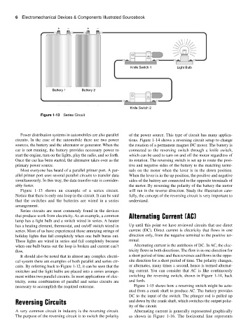
+ − + −
Knife Switch 1 Light Bulb
Battery 1 Battery 2
Knife Switch 2
Figure 1-13 Series Circuit
Power distribution systems in automobiles are also parallel of the power source. This type of circuit has many applica-
circuits. In the case of the automobile there are two power tions. Figure 1-14 shows a reversing circuit setup to change
sources, the battery and the alternator or generator. When the the rotation of a permanent magnet DC motor. The battery is
car is not running, the battery provides necessary power to connected to the reversing switch through a knife switch,
start the engine, turn on the lights, play the radio, and so forth. which can be used to turn on and off the motor regardless of
Once the car has been started, the alternator takes over as the its rotation. The reversing switch is set up to route the posi-
primary power source. tive and negative sides of the battery to the matching termi-
Most everyone has heard of a parallel printer port. A par- nals on the motor when the lever is in the down position.
allel printer port uses several parallel circuits to transfer data When the lever is in the up position, the positive and negative
simultaneously. In this way, the data transfer rate is consider- sides of the battery are connected to the opposite terminals of
ably faster. the motor. By reversing the polarity of the battery the motor
Figure 1-13 shows an example of a series circuit. will run in the reverse direction. Study the illustration care-
Notice that there is only one loop in the circuit. It can be said fully, the concept of the reversing circuit is very important to
that the switches and the batteries are wired in a series understand.
arrangement.
Series circuits are most commonly found in the devices
that produce work from electricity. As an example, a common Alternating Current (AC)
lamp has a light bulb and a switch wired in series. A heater
has a heating element, thermostat, and on/off switch wired in Up until this point we have reviewed circuits that use direct
series. Most of us have experienced those annoying strings of current (DC). Direct current is electricity that flows in one
holiday lights that fail completely when one bulb burns out. direction only, from the negative terminal to the positive ter-
These lights are wired in series and fail completely because minal.
when one bulb burns out the loop is broken and current can’t Alternating current is the antithesis of DC. In AC, the elec-
flow. tricity flows in both directions. The flow is in one direction for
It should also be noted that in almost any complex electri- a short period of time and then reverses and flows in the oppo-
cal system there are examples of both parallel and series cir- site direction for a short period of time. The polarity changes,
cuits. By referring back to Figure 1-12, it can be seen that the or alternates, many times a second, hence is termed alternat-
switches and the light bulbs are placed into a series arrange- ing current. You can consider that AC is like continuously
ment within two parallel circuits. In most applications of elec- switching the reversing switch, shown in Figure 1-14, back
tricity, some combination of parallel and series circuits are and forth.
necessary to accomplish the required outcome. Figure 1-15 shows how a reversing switch might be actu-
ated from a crank shaft to produce AC. The battery provides
DC to the input of the switch. The plunger rod is pulled up
Reversing Circuits and down by the crank shaft, which switches the output polar-
ity of the circuit.
A very common circuit in industry is the reversing circuit. Alternating current is generally represented graphically
The purpose of the reversing circuit is to switch the polarity as shown in Figure 1-16. The horizontal line represents