
Page 48 - Electromechanical Devices and Components Illustrated Sourcebook
P. 48
10 Electromechanical Devices & Components Illustrated Sourcebook
If we think back, most of us can remember learning about The Lever
mechanics in our high school physics classes. Basic mechan-
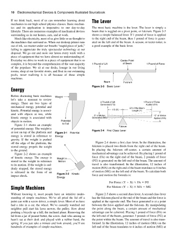
ics and its application is imperative to our day-to-day The most basic machine is the lever. The lever is simply a
lifestyle. There are numerous examples of mechanical devices beam that is toggled on a pivot point, or fulcrum. Figure 2-3
surrounding us in our homes, cars, and at work. shows a simple balanced lever. If 1 pound of force is applied
Much like electricity, most of us give little or no thought to to the right end of the beam, then 1 pound of force is gener-
the machines that surround us. When our desktop printer runs ated on the left end of the beam. A seesaw, or teeter-totter, is
out of ink, we mutter under our breaths “stupid piece of junk,” a good example of the basic lever.
failing to appreciate the truly spectacular technology at our
disposal. We go out and mow our lawns every week with a
piece of equipment that we have almost no understanding of.
Everyday we drive to work in a piece of equipment that is so Center Point
complex, it is beyond the comprehension of the vast majority 1 Pound of Lift of Beam 1 Pound of Force
of the populace. We sit at our desks, lounge in our living
rooms, shop at our favorite stores, and float in our swimming
pools, never realizing it is all because of these simple
machines.
Beam Fulcrum
Figure 2-3 Basic Lever
Energy
Before discussing basic machines Weight
let’s take a moment to review
energy. There are two types of 2 Pounds of Lift 1 Pound of Force
Generated (FG) Applied (FA)
mechanical energy, potential and
2/3 of the Beam
kinetic. Potential energy is associ- 1/3 (X) Length (Y)
ated with objects at rest, while
6" of Motion 12" of Motion
kinetic energy is associated with Generated (MG) Applied (MA)
objects in motion. Potential
Figure 2-1 shows an example to Fall
Fulcrum
of potential energy. The weight is
Figure 2-4 First Class Lever
at rest on top of the platform and Figure 2-1 Potential
energy is stored in reference to Energy
gravity. If the weight is pushed
off the edge of the platform, the Figure 2-4 shows a first class lever. In the illustration, the
stored energy propels the weight fulcrum is placed two-thirds from the right end of the beam.
to the ground. In placing the fulcrum off-center, a certain amount of
Figure 2-2 shows an example mechanical advantage can be achieved. By placing 1 pound of
of kinetic energy. The energy is Weight in force (FA) on the right end of the beam, 2 pounds of force
stored in the weight in reference Motion (FG) is generated on the left end of the beam. The amount of
to its motion. If the weight is sud- travel is also transformed. In the illustration, 12 inches of
denly stopped, the stored energy motion (MA) on the right end of the beam translates to 6 inches
is released in the form of an of motion (MG) on the left end of the beam. To calculate both
Figure 2-2 Kinetic
impact shock. force and motion the formula is:
Energy
For Force: (Y X) FA FG
Simple Machines For Motion: (Y X) MA MG
Without knowing it, most people have an intuitive under- Figure 2-5 shows a second class lever. A second class lever
standing of simple machines. We’ve all pried the lid off a has the fulcrum placed at the end of the beam and the force is
paint can with a screw driver, a simple lever. Most of us have applied at the opposite end. The force generated is at a point
had a ride in a car, the wheel. We’ve casually watched our between the force applied and the fulcrum. By manipulating
neighbor pull start his lawn mower, the pulley. How about the point along the beam, a certain amount of mechanical
pushing a bicycle up a hill, the inclined plane. Removing the advantage can be achieved. Placing 1 pound of force (FA) on
lid from a jar of peanut butter, the screw. And who among us the left end of the beam, generates 3 pounds of force (FG) at
hasn’t sat at their desk and played with a rubber band, the the point within the beam. The amount of travel is also trans-
spring. If you just take a minute and look around, you’ll see formed. In the illustration, 12 inches of motion (MA) on the
hundreds of examples of simple machines. left end of the beam translates to 4 inches of motion (MG) at