Page 52 - Electromechanical Devices and Components Illustrated Sourcebook
P. 52

14 Electromechanical Devices & Components Illustrated Sourcebook


                     Solinoid                                                         31.36" of Motion
                                                                                      Applied (MA)
                                                                12" of Vertical  25 Pounds of Force
                                                              Motion Generated    Applied (FA)           100 Pounds
                                                                  (VMG)
                                                                                                         of Load (W)
                                                                                 22.5° (A)
                                             Cable

                                                                                28.97" of Horizontal Motion
                                                                                   Generated (HMG)
                                         Pullys
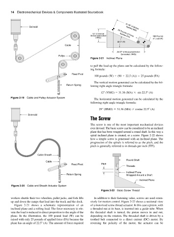
                                                              Figure 2-21 Inclined Plane
                                                              to pull the load up the plane can be calculated by the follow-
                                                              ing formula:
                                                  Fixed Pivot
                                                                 100 pounds (W)   (90   22.5 (A))   25 pounds (FA)
                                                                 The vertical motion generated can be calculated by the fol-
                                              Return Spring   lowing right angle triangle formula:
                                                                     12" (VMG)   31.36 (MA)   sin 22.5  (A)

        Figure 2-19 Cable and Pulley Actuator System
                                                                 The horizontal motion generated can be calculated by the
                                                              following right angle triangle formula:

                                                                    29" (HMG)   31.36 (MA)   cosine 22.5  (A)
                    Solenoid
                                                              The Screw

                                                              The screw is one of the most important mechanical devices
                                                              ever devised. The basic screw can be considered to be an inclined
                                                              plane that has been wrapped around a round shaft. In this way a
                                                              spiral inclined plane is created, or a screw. Figure 2-22 shows
                                                              how a simple screw is generated with an inclined plane. The
                                                              progression of the spirals is referred to as the pitch, and the
                                                              pitch is generally referred to in threads per inch (TPI).


                          Cable Sheath
                                                                                       Round Shaft
                                Cable
                                                 Fixed Pivot          Pitch
                                                                                       Threads
                                                                                       Inclined Plane
                                              Return Spring                            Wrapped Around a Shaft

                                                                                                Inclined Plane
         Figure 2-20 Cable and Sheath Actuator System
                                                                      Figure 2-22 Basic Screw Thread

        workers shuttle their two wheelers, pallet jacks, and fork lifts  In addition to their fastening value, screws are used exten-
        up and down the ramps that lead into the truck and the dock.  sively for motion control. Figure 2-23 shows a sectional view
           Figure 2-21 shows a schematic representation of an  of a motorized screw thread actuator. In this case a piston, with
        inclined plane and a rolling load. The force necessary to ele-  a threaded nut at its base, is inserted into a guide tube. When
        vate the load is reduced in direct proportion to the angle of the  the threaded shaft is turned, the piston moves in and out,
        plane. In the illustration, the 100 pound load (W) can be  depending on the rotation. The threaded shaft is driven by a
        raised with only 25 pounds of applied force (FA) because the  toothed belt connected to a direct current (DC) motor. By
        plane has an angle of 22.5  (A). The amount of force required  reversing the polarity of the motor, the actuator can be
   47   48   49   50   51   52   53   54   55   56   57