
Page 49 - Electromechanical Devices and Components Illustrated Sourcebook
P. 49
Chapter 2 Basic Mechanics 11
1 Pound of Force Connecting Rod
Applied (FA)
Total Beam Length (L)
3 Pounds of Force Generated (FG)
First Class
2/3 of the Beam Length 1/3 (X) Lever
Fixed Pivot Fixed Pivot
12" of Motion
Applied (MA)
4" of Motion Fulcrum Figure 2-7 Levers and Connecting Rods
Generated (MG)
Beam
Figure 2-5 Second Class Lever
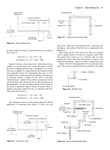
class levers, which are interconnected with a connecting rod.
In doing so, the motion of the left lever is duplicated in the
the point within the beam. To calculate both force and motion right lever.
the formula is: Bell cranks are 90 , first class levers. They are typically
used to change direction of motion in a linkage system. Most
For Force: (L X) FA FG bell cranks have a ratio of 1 to 1; however, they are often
For Motion: (L X) MA MG applied with other ratios that will increase or decrease the
mechanical advantage. Figure 2-8 shows a simple bell crank.
Figure 2-6 shows a third class lever. A third class lever is Figure 2-9 shows an arrangement of levers and connecting
similar to a second class lever, except the points at which rods. The motion is supplied from the solenoid at the upper
the force is applied and the force is generated are reversed.
The force is applied at a point between the fulcrum and the
Right / Left Motion
force generation point. By manipulating the point of force
along the beam a certain amount of mechanical advantage can
be achieved. Placing 3 pounds of force (FA) at the point
within the beam, 1 pound of force (FG) is generated at the left Fixed Pivot
end of the beam. The amount of travel is also transformed. In
the illustration, 12 inches of motion (MG) on the left end of
the beam is generated when 4 inches of motion (MA) is Up / Down Motion
applied at the point within the beam. To calculate both force Figure 2-8 90 Bell Crank
and motion the formula is:
For Force: (L X) FA FG
For Motion: (L X) MA MG Connecting Rod
The usefulness of levers can be greatly enhanced with the
application of connecting rods. Figure 2-7 shows two first Solenoid Third Class Lever
Fixed Pivot
1 Pound of Force First Class
Fixed Pivot
Generated (FG) Lever
Total Beam Length (L) Return Spring
3 Pounds of Force Applied (FA) Connecting Rod
2/3 of the
Beam Length 1/3 (X) Fixed Pivot Fixed Pivot
Bell Crank
Fulcrum
12" of Motion
Generated (FG) Second Class Lever
Return Spring
4" of Motion
Applied (MG)
Beam
Figure 2-6 Third Class Lever Figure 2-9 Levers and Connecting Rods