Page 50 - Electromechanical Devices and Components Illustrated Sourcebook
P. 50

12 Electromechanical Devices & Components Illustrated Sourcebook

        left. Study the illustration carefully and follow the motion of  Pulleys
        the linkage. Also notice that return springs are applied at both
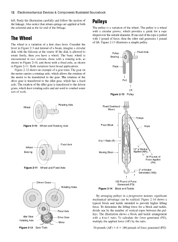
        the solenoid and at the far end of the linkage.       The pulley is a variation of the wheel. The pulley is a wheel
                                                              with a circular groove, which provides a guide for a rope
                                                              draped over the outside diameter. If one end of the rope is pulled
        The Wheel                                             with 1 pound of force, then the other end generates 1 pound
                                                              of lift. Figure 2-13 illustrates a simple pulley.
        The wheel is a variation of a first class lever. Consider the
        lever in Figure 2-3 and instead of a beam, imagine a circular
        disk with the fulcrum at the center. If the disk is allowed to                      Fixed Axle
                                                                           Pulley
        rotate freely, then you have a wheel.  The basic wheel is
                                                                          Bearing
        encountered in two versions, those with a rotating axle, as
        shown in Figure 2-10, and those with a fixed axle, as shown
        in Figure 2-11. Both variations have broad applications.            Rope
           Figure 2-12 shows an example of a gear train. The gear on
        the motor carries a rotating axle, which allows the rotation of
        the motor to be transferred to the gear. The rotation of the
        drive gear is transferred to the idler gear, which has a fixed             Pull
        axle. The rotation of the idler gear is transferred to the driven
        gears, which have rotating axles and are used to conduct some
                                                                                       Lift
        sort of work.
                                                                          Figure 2-13 Pulley


                                        Rotating Axle
                 Wheel                                               Fixed Overhead
                                                                         Mount

                                                                                           Pulleys


                 Figure 2-10 Wheel and Rotating Axle                Fixed Block                  Rope


                                                                  6 to 1 Ratio (R)
                                         Fixed Axle
                  Wheel
                                                                                         12" of Motion
                 Bearing                                           Moving Block          Applied (MA)
                                                                                                  30 Pounds of
                                                                                                  Force Applied
                                                                                                     (FA)
                 Figure 2-11 Wheel and Fixed Axle
                                                                                             2" of Motion
                                                                                             Generated (MG)


                         Driven Gears                                        180 Pound of Force
                                                                               Generated (FG)
                                          Rotating Axles
                                                                  Figure 2-14 Block and Tackle
                                                                 By arranging pulleys in a progressive manner, significant
                                                              mechanical advantage can be realized. Figure 2-14 shows a
                                                              typical block and tackle intended to provide higher lifting
                                                              force. To determine the lifting force for a block and tackle,
                                                              divide one by the number of vertical ropes between the pul-
                                       Fixed Axle
                                                              leys. The illustration shows a block and tackle arrangement
                Idler Gear             Drive Gear             with a 6-to-1 ratio.  To calculate the force generated (FG),
              Rotating Axle                                   multiply the applied force (AF) by the ratio.
                                        Motor

              Figure 2-12 Gear Train                           30 pounds (AF)   6   180 pounds of force generated (FG)
   45   46   47   48   49   50   51   52   53   54   55