
Page 57 - Electromechanical Devices and Components Illustrated Sourcebook
P. 57
Chapter 3 Power Sources 19
for each voltage, only the amplitude changes. A visual refer- First Phase
ence for the level of power that each voltage can supply can 1/60 Sec Second Phase
be gauged by comparing the area above the zero-volt line and Third Phase
within the curve, with a larger area representing higher
power.
Some countries around the world use 50 Hz AC power. For Zero volts
all practical purposes there is very little difference between 50
and 60 Hz Power; the most significant difference is that
induction motors operate at a slower speed when using 50 Hz 1/180 Sec
power. Most heating equipment provides the same output
1/90 Sec
with 60 or 50 Hz. Other industrial equipment, such as arc
welding machines and power supplies, show very little differ- Figure 3-5 Three-Phase Wave Form
ence in their output.
To limit the weight of electromagnetic equipment, 400 Hz
power is utilized. Power of 400 Hz is used primarily on air-
craft where low weight is critical.
3 Phase Power
Figure 3-4 shows 50, 60, and 400 Hz wave forms. Note that
the voltage, or amplitude, is the same for all three frequencies.
It should also be noted that the overall power is the same for
Load
each frequency. The difference in frequency is only critical
when considering the amount of iron that is used in the com-
ponent to be driven. This consideration will be discussed in
greater detail in Chapter 5.
Corner Connection
Figure 3-6 Delta Configuration
60 Hz 50 Hz
There are two different types of connections that can be
Zero volts
used with three-phase. These configurations are referred to
as Delta and Wye. Figure 3-6 shows a Delta configuration.
In this setup the three loads are electrically arranged in a tri-
angle and the power connections are made to the three cor-
400 Hz
ners. Figure 3-7 shows a Wye configuration. With this
Figure 3-4 50, 60, and 400 Hz Waveform arrangement the three loads are electrically arranged in a Y
and the power connections are made at the end of the loads.
Wye configurations generally have a fourth “return” wire as
shown.
Three-Phase Three-phase power also has significant advantages when
dealing with induction motors. This attribute will be discussed
Alternating current power is generally delivered in two differ-
further in Chapter 6.
ent forms, single-phase and three-phase. All of the previous
In the same way that three-phase power is utilized, higher
examples of AC shown in this chapter of the book are single-
numbers of phases can also be configured. Figure 3-8 shows
phase. Generally, three-phase is used for power generation
a six-phase graphic. The frequency is 60 Hz and the delay
and distribution. Applications for three-phase power are nor- 1
time is / 360 of a second or a phase angle of 60 .
mally in the commercial and industrial communities.
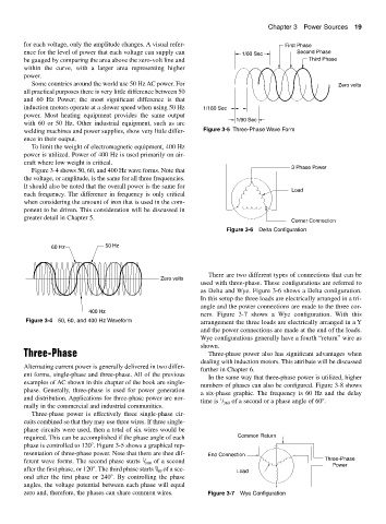
Three-phase power is effectively three single-phase cir-
cuits combined so that they may use three wires. If three single-
phase circuits were used, then a total of six wires would be
required. This can be accomplished if the phase angle of each Common Return
phase is controlled to 120 . Figure 3-5 shows a graphical rep-
resentation of three-phase power. Note that there are thee dif- End Connection
1
ferent wave forms. The second phase starts / 180 of a second Three-Phase
Power
1
after the first phase, or 120 . The third phase starts / of a sec- Load
90
ond after the first phase or 240 . By controlling the phase
angles, the voltage potential between each phase will equal
zero and, therefore, the phases can share common wires. Figure 3-7 Wye Configuration