
Page 58 - Electromechanical Devices and Components Illustrated Sourcebook
P. 58
20 Electromechanical Devices & Components Illustrated Sourcebook
Phase 1 Batteries are generally rated using two parameters. The
Phase 2 first, and most obvious, is voltage. The second, and less intu-
Phase 3
Phase 4 itive, is amp-hours. Amp-hours indicate the maximum current
1/60 Sec Phase 5 that a battery can continuously deliver for a period of 1 hour.
Phase 6 When a battery is discharged at this rate, usually it’s full
charge will be expended. A battery that has a 250 amp-hour
rating is capable of delivering 250 amps at the batteries full
voltage for 1 hour. A battery that has a 500 mA-hour rating is
Zero
volts capable of delivering 1/2 amp for 1 hour. It should also be
noted that the amp-hour rating is an indication of the capacity
1/360 Sec of battery. If our 250 amp-hour battery is discharged at a rate
of 2 amps, its charge life will be 125 hours. Similarly, if we
Figure 3-8 Six-Phase Wave Form
discharge the battery at 375 amps, the charge life will be 0.66
hours or 39.6 minutes.
Amp-Hours Discharge Rate Charge Life
Batteries Another figure we see on automotive batteries is “cold
cranking amps.” This figure is generally higher than the amp-
The most common and the most intuitively understandable hour rating. This rating refers to the maximum current that the
electrical power source is the battery. Batteries are an excel- battery can deliver at full charge for a short period of time.
lent source of DC electricity. They are easy to understand and This is a loose standard and shouldn’t be relied on when
make sense to the casual observer. They are inexpensive, rea- selecting a battery for peak demand applications. It should
sonably light weight, and are available in a variety of differ- also be noted that when a battery is pressed into this type of
ent configurations that are appropriate for all manner of service, it can get fairly hot and a long cool down period is
applications. required.
Lead/Acid Batteries
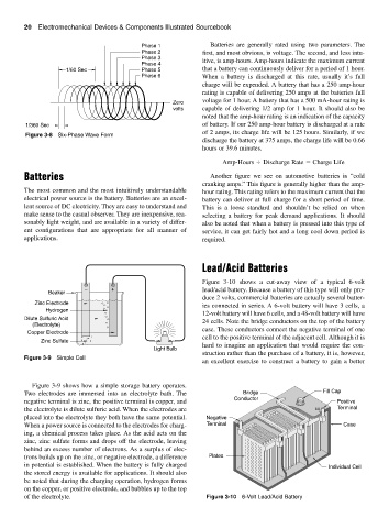
Figure 3-10 shows a cut-away view of a typical 6-volt
− + lead/acid battery. Because a battery of this type will only pro-
Beaker
duce 2 volts, commercial batteries are actually several batter-
Zinc Electrode
ies connected in series. A 6-volt battery will have 3 cells, a
Hydrogen
12-volt battery will have 6 cells, and a 48-volt battery will have
Dilute Sulfuric Acid 24 cells. Note the bridge conductors on the top of the battery
(Electrolyte)
case. These conductors connect the negative terminal of one
Copper Electrode
cell to the positive terminal of the adjacent cell. Although it is
Zinc Sulfate
hard to imagine an application that would require the con-
Light Bulb
struction rather than the purchase of a battery, it is, however,
Figure 3-9 Simple Cell
an excellent exercise to construct a battery to gain a better
Figure 3-9 shows how a simple storage battery operates.
Two electrodes are immersed into an electrolyte bath. The Bridge Fill Cap
negative terminal is zinc, the positive terminal is copper, and Conductor Positive
the electrolyte is dilute sulfuric acid. When the electrodes are Terminal
placed into the electrolyte they both have the same potential. Negative
When a power source is connected to the electrodes for charg- Terminal Case
ing, a chemical process takes place. As the acid acts on the
zinc, zinc sulfate forms and drops off the electrode, leaving
behind an excess number of electrons. As a surplus of elec-
trons builds up on the zinc, or negative electrode, a difference Plates
in potential is established. When the battery is fully charged Individual Cell
the stored energy is available for applications. It should also
be noted that during the charging operation, hydrogen forms
on the copper, or positive electrode, and bubbles up to the top
of the electrolyte. Figure 3-10 6-Volt Lead/Acid Battery