
Page 63 - Electromechanical Devices and Components Illustrated Sourcebook
P. 63
Chapter 3 Power Sources 25
used under the hood of a car or truck. They have two short
1100 cables with high current terminal clamps. The case of the
Discharged tester is ventilated to release the heat that is generated during
testing.
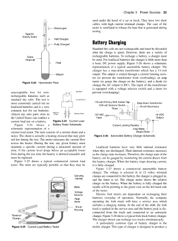
Specific 1200
Gravity Scale
Half Charged
Battery Charging
Fully Charged
1300
Standard dry cells are not rechargeable and must be discarded
after the charge is spent. However, there are a variety of
rechargeable batteries. To recharge a battery, a charger must
Glass
Ampoule be used. For lead/acid batteries the charger is little more than
Float a basic DC power supply. Figure 3-26 shows a schematic
representation of a typical automobile battery charger. The
charger has a step-down transformer which has a 14-volt
Weight output. The output is routed through a current limiting resis-
tor (to prevent the transformer from overloading), an amp
meter (to gauge the charge on the battery), and a diode (to
Figure 3-23 Hydrometer Float
change the AC output to DC). The input of the transformer
is equipped with a voltage selector switch and a timer (to
unacceptable loss for non- Ma Meter prevent overcharging).
rechargeable batteries such as
standard dry cells. The test is Current Shunt
115-volt Primary With Center Tap
most commonly carried out on Step-Down Transformer
12/6-volt Selector Switch
lead/acid batteries and is a very 14-volt Secondary
Timer
common test for car batteries. −
Negative T
Almost any auto parts store in Probe Positive Probe 120-VAC 14-VDC
the United States can conduct a Input Output
current load test on a battery. Figure 3-24 Current Load +
Figure 3-24 shows a Battery Tester Schematic Current Limiting Resistor
schematic representation of a Amp Meter
current load tester. The unit consists of a current shunt and a Single Diode
meter. The shunt is actually a heating element that may glow Figure 3-26 Automobile Battery Charger Schematic
red hot during the test. The meter measures the current flow
across the heater. During the test, any given battery must
maintain a specific current during a measured amount of Lead/acid batteries have very little internal resistance
time. If the current level drops below an acceptable lower when they are discharged. Their internal resistance increases
limit during the test time the battery is deemed unusable and as the charge state increases. Therefore, the charge state of the
must be replaced. battery can be gauged by monitoring the current drawn from
Figure 3-25 shows a typical commercial current load the battery charger. When the battery stops drawing current,
tester. The units are typically portable so that they may be it is fully charged.
Figure 3-27 shows a commercial automobile battery
charger. The voltage is selected (6 or 12 volts), terminal
Carrying clamps are connected to the battery, the charger is plugged in,
Handle
and the timer is set. The charge meter shows the relative
charge on the battery. When the battery is fully charged the
Recharge
Replace Good
Meter needle will be pointing to the green zone on the left hand side
of the meter.
Voltage
Selector Electric fork trucks are dependent on recharging their
6 Volt 12 Volt
batteries everyday of operation. Normally, the company
Heat
Vents operating the fork truck will have a service area which
includes a charging station. At the end of the shift, the fork
Shunt
Housing truck is parked in the service area and the battery pack is dis-
connected from the truck and connected to an automatic
Terminal charger. Figure 3-28 shows a typical fork truck battery charger.
Clamps
The charger shown can recharge two trucks simultaneously.
A particularly common type of battery charger is the
Figure 3-25 Current Load Battery Tester trickle charger. This type of charger is designed to produce a