
Page 65 - Electromechanical Devices and Components Illustrated Sourcebook
P. 65
Chapter 3 Power Sources 27
There are three methods commonly used for controlling It should be noted that NiCad batteries will greatly benefit
the charge of a NiCad Battery. The first, and most common, is from a proper charging program. NiCad batteries should
to monitor the voltage of the battery. When the battery always be stored fully charged. They should be completely
achieves full voltage it is at maximum charge. The voltage of discharged and fully recharged on a periodic basis. They
a NiCad battery will continuously rise until it reaches full should never be subjected to over charging and under charg-
charge and if the charging is continued the battery voltage will ing should be avoided. If a NiCad battery is properly handled,
start to fall. Generally, a NiCad charger will incorporate an it will provide many years of excellent service. Inversely, if
electronic monitoring circuit that watches the voltage rise of the batteries are mishandled, their useful service life will be
the battery. As long as the voltage continues to rise, the charge dramatically shortened.
will continue. When the monitoring circuit detects a slight Nickel/metal hydride or NiHd batteries have become the
drop in voltage, the charging is stopped and the battery is at rechargeable battery of choice for most rechargeable applica-
full charge. tions. This battery formulation provides some significant
The second, and less reliable method, is to monitor the advantages over NiCad batteries, most noteworthy, an
temperature of the battery. NiCad batteries will remain cool improved capacity. Charging these batteries is principally the
until they reach their peak charge. At this point they will start same as for NiCad batteries, except complete discharge
to heat up. The temperature of the battery can be monitored should be avoided with NiHd batteries. Charge rates vary with
and when there is a rise, the charging is stopped. NiHd batteries but usually match mAh rating. The charge of
The third, and most straightforward method, is to charge battery is assessed by measuring voltage. If a NiHd battery is
the battery in reference to its amp-hour rating. In order to time fully discharged, it should be placed on a trickle charger for a
charge a NiCad battery, it must be completely discharged first. period of time specified by the manufacturer before receiving
Then 1.5 times its amp-hour rating can be applied for 1 hour a higher charge rate. In any case, the batteries may be fully
and the battery will be up to full charge. charged in 6 to 14 hours with a typical trickle charger.
Battery Holders
Automatic Resetting Power Switch
1 Hr Delay-Off Timer
When using batteries it is necessary to mount them in a con-
AC Input
Charge Only T venient and secure manner that is appropriate for the applica-
Button Discharge/Charge
Button tion. Commercial holders are available for most standard bat-
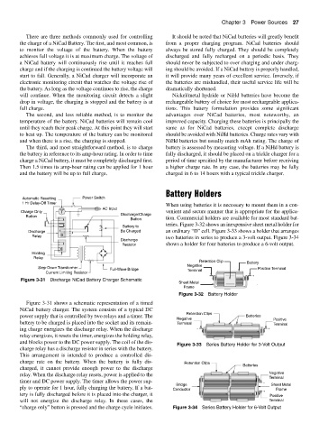
+ Battery to teries. Figure 3-32 shows an inexpensive sheet metal holder for
Discharge − Be Charged an ordinary “D” cell. Figure 3-33 shows a holder that arranges
Relay two batteries in series to produce a 3-volt output. Figure 3-34
Discharge
Resistor shows a holder for four batteries to produce a 6-volt output.
Holding
Relay
Retention Clip Battery
Negative
Step-Down Transformer
Full-Wave Bridge Terminal Positive Terminal
Current Limiting Resistor
− +
Figure 3-31 Discharge NiCad Battery Charger Schematic +
Sheet Metal
Frame
Figure 3-32 Battery Holder
Figure 3-31 shows a schematic representation of a timed
NiCad battery charger. The system consists of a typical DC
Retention Clips
power supply that is controlled by two relays and a timer. The Batteries
Negative Positive
battery to be charged is placed into the socket and its remain- Terminal Terminal
ing charge energizes the discharge relay. When the discharge − +
+ +
relay energizes, it resets the timer, energizes the holding relay,
and blocks power to the DC power supply. The coil of the dis-
Figure 3-33 Series Battery Holder for 3-Volt Output
charge relay has a discharge resistor in series with the battery.
This arrangement is intended to produce a controlled dis-
charge rate on the battery. When the battery is fully dis- Retention Clips Batteries
charged, it cannot provide enough power to the discharge
relay. When the discharge relay resets, power is applied to the Negative
Terminal
timer and DC power supply. The timer allows the power sup- + + −
Bridge Sheet Metal
ply to operate for 1 hour, fully charging the battery. If a bat- Conductor + Frame
tery is fully discharged before it is placed into the charger, it + + Positive
will not energize the discharge relay. In these cases, the Terminal
“charge only” button is pressed and the charge cycle initiates. Figure 3-34 Series Battery Holder for 6-Volt Output