
Page 68 - Electromechanical Devices and Components Illustrated Sourcebook
P. 68
30 Electromechanical Devices & Components Illustrated Sourcebook
Communications Antenna
Strobe Light
Rain Cap
Solar Panel
Solar Panel
Mast
Access Hatch
Water Line
Battery Pack
Float
Adjustable Mount
Ground Pole
Column
Dead Weight
Equipment Housing Anchor Cable
Ground Wire
To Ground Sensor Figure 3-45 Flashing Marine Buoy with Solar
Powered Battery Charger
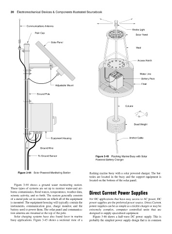
Figure 3-44 Solar Powered Monitoring Station flashing marine buoy with a solar powered charger. The bat-
teries are located in the buoy and the support equipment is
located on the bottom of the solar panel.
Figure 3-44 shows a ground water monitoring station.
These types of systems are set up to monitor water-and air-
borne contaminates, flood waters, temperatures, weather data, Direct Current Power Supplies
seismic activity, and so forth. The system generally consists
of a metal pole set in concrete on which all of the equipment For DC applications that have easy access to AC power, DC
is mounted. The equipment housing will typically contain the power supplies are the preferred power source. Direct Current
instruments, communication gear, charge monitor, and the power supplies can be as simple as a trickle charger or may be
battery used to power them. The solar panel and communica- extremely complex, computer controlled units that are
tion antenna are mounted at the top of the pole. designed to supply specialized equipment.
Solar charging systems have also found favor in marine Figure 3-46 shows a half-wave DC power supply. This is
buoy applications. Figure 3-45 shows a sectional view of a probably the simplest power supply design that is in common