
Page 71 - Electromechanical Devices and Components Illustrated Sourcebook
P. 71
Chapter 3 Power Sources 33
Three-Phase Step-Down Full-Wave Bridge Step-Down Full-Wave Bridge
Transformer
Transformer
Input Common
−
− Regulated
AC Input + Output
+
Three-Phase
AC Input UnFiltered Output
DC Output Filter Capacitor
Voltage Regulator
Filter Capacitor
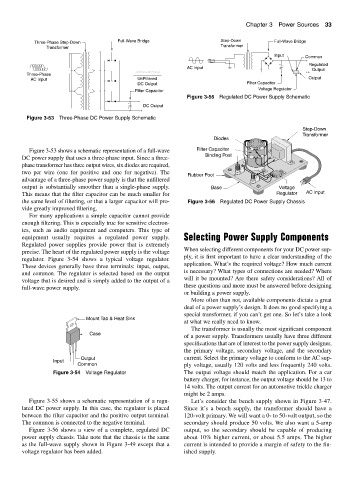
Figure 3-55 Regulated DC Power Supply Schematic
−
− DC Output
+
+
Figure 3-53 Three-Phase DC Power Supply Schematic
Step-Down
Transformer
Diodes
Figure 3-53 shows a schematic representation of a full-wave Filter Capacitor
Binding Post
DC power supply that uses a three-phase input. Since a three-
phase transformer has three output wires, six diodes are required,
two per wire (one for positive and one for negative). The
Rubber Foot
advantage of a three-phase power supply is that the unfiltered
output is substantially smoother than a single-phase supply. Base Voltage
This means that the filter capacitor can be much smaller for Regulator AC Input
the same level of filtering, or that a larger capacitor will pro- Figure 3-56 Regulated DC Power Supply Chassis
vide greatly improved filtering.
For many applications a simple capacitor cannot provide
enough filtering. This is especially true for sensitive electron-
ics, such as audio equipment and computers. This type of
equipment usually requires a regulated power supply. Selecting Power Supply Components
Regulated power supplies provide power that is extremely
When selecting different components for your DC power sup-
precise. The heart of the regulated power supply is the voltage
ply, it is first important to have a clear understanding of the
regulator. Figure 3-54 shows a typical voltage regulator.
application. What’s the required voltage? How much current
These devices generally have three terminals: input, output,
is necessary? What types of connections are needed? Where
and common. The regulator is selected based on the output
will it be mounted? Are there safety considerations? All of
voltage that is desired and is simply added to the output of a
these questions and more must be answered before designing
full-wave power supply.
or building a power supply.
More often than not, available components dictate a great
deal of a power supply’s design. It does no good specifying a
special transformer, if you can’t get one. So let’s take a look
Mount Tab & Heat Sink
at what we really need to know.
The transformer is usually the most significant component
Case
of a power supply. Transformers usually have three different
specifications that are of interest to the power supply designer,
the primary voltage, secondary voltage, and the secondary
Output current. Select the primary voltage to conform to the AC sup-
Input
Common ply voltage, usually 120 volts and less frequently 240 volts.
Figure 3-54 Voltage Regulator The output voltage should match the application. For a car
battery charger, for instance, the output voltage should be 13 to
14 volts. The output current for an automotive trickle charger
might be 2 amps.
Figure 3-55 shows a schematic representation of a regu- Let’s consider the bench supply shown in Figure 3-47.
lated DC power supply. In this case, the regulator is placed Since it’s a bench supply, the transformer should have a
between the filter capacitor and the positive output terminal. 120-volt primary. We will want a 0- to 50-volt output, so the
The common is connected to the negative terminal. secondary should produce 50 volts. We also want a 5-amp
Figure 3-56 shows a view of a complete, regulated DC output, so the secondary should be capable of producing
power supply chassis. Take note that the chassis is the same about 10% higher current, or about 5.5 amps. The higher
as the full-wave supply shown in Figure 3-49 except that a current is intended to provide a margin of safety to the fin-
voltage regulator has been added. ished supply.