
Page 76 - Electromechanical Devices and Components Illustrated Sourcebook
P. 76
38 Electromechanical Devices & Components Illustrated Sourcebook
Electrical controls are the most common class of electrome-
chanical devices. This arena, that comprises primarily switching
devices, impacts virtually every aspect of our technical lives. We
are all familiar with switching devices, every time we flip a light
switch, we use one. When you turn the key to start your car, you Schematic Symbol
use a switching device that, in turn, actuates a multitude of other
switching devices. When you pick up the receiver on the phone,
Blade Handle
a switch activates the set. To better understand electromechani-
cal devices, it is imperative that the reader understands control Pivot
mechanisms. This chapter of the book provides a review of these Contact B Contact A
mechanisms and their associated terminologies. Terminal B Terminal A
Base
Manual Switches Common Terminal
Figure 4-2 Single-Pole, Double Throw Knife Switch
Manually actuated switches are by far the most common elec-
trical control devices. The simplest switch is the knife switch,
as shown in Figure 4-1. The knife switch is simply a metal
blade that can be rotated into a contact. The switch terminals
are located at either end of the blade, on the pivot and on the
contacts. To turn on the switch you simply push the blade into
the contacts. To turn off the switch, lift the blade out of the
contacts. In real life the basic knife switch is not very common.
They are primarily used to switch high-power applications
and for educational purposes.
Schematic Symbol
Off
On
Handle
Insulating Bridge
Base
Contacts
Pole 1
Schematic Symbol
Pole 2
Figure 4-3 Double-Pole, Single Throw Knife Switch
Blade Handle
Pivot
Terminal Contact
Terminal
Thumb Nut
Base
Figure 4-1 Single-Pole, Single Throw Knife Switch
A double throw switch is essentially a bidirectional valve Schematic Symbol
for electricity. Power is connected to the common terminal
and may be directed to one or another circuits. Figure 4-2
shows a single-pole, double throw knife switch. By throwing Off
the blade to the right or left, the common terminal can be On Handle
connected to either contact A or B. Insulating Bridge
Multipole switches are intended to switch two or more
On
circuits simultaneously. Figure 4-3 shows a two-pole knife Base
switch. This switch is simply two standard switches with a Contacts A
common handle and mounted on a common base.
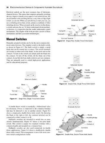
Multipole switches are also used extensively in double Commons
throw applications. Figure 4-4 shows a double-pole, double Pole 1 Contacts B
throw knife switch. This arrangement is one of the most com- Pole 2
mon switch configurations found. Figure 4-4 Double-Pole, Double Throw Knife Switch