
Page 77 - Electromechanical Devices and Components Illustrated Sourcebook
P. 77
Chapter 4 Electrical Controls 39
Contacts
Handle
Knife
Pivot
Terminals
Base
Schematic Symbol
Off
On
Handle Figure 4-7 Bench Built Knife Switch
On Insulating Bridge
Base
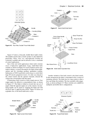
Brass Thumb Nut
Contacts A Shrink Wrap Handle
Copper Knife
Pole 1 Commons Brass Hex Nut
Pole 2
Pole 3 Contacts B
Pole 4 Brass Flat Washer
Copper
Figure 4-5 Four-Pole, Double Throw Knife Switch
Pivot
Copper Contact
Copper Rivet
Base
Figure 4-5 shows a four-pole, double throw knife switch.
The number of poles that a switch can have is only limited by
practicality. Three-, four-, six-, and eight-pole switches are
commonly available and can be utilized to solve a multitude
of control applications.
Long Brass Screw
One of the real world applications where knife switches Short Brass Screw
excel, is high-power applications. Large, multi-blade knife
switches as shown in Figure 4-6 can be found in power gen-
Figure 4-8 Knife Switch Exploded View
eration stations, as power disconnects for high-current appli-
cations and for switching auxiliary generation systems.
Submarines of WWII used knife switch arrays to control their
large DC electric propulsion motors. An order was relayed to
Another variation of the knife switch is the fused switch.
the control station and the operator manually selected the
In this arrangement the blade is interrupted with a section of
voltage that corresponded with that speed.
insulating material. The blade has two snap sockets so that a
Constructing a knife switch is a fairly simple process. Four
fuse can bridge the insulator. The fuse assembly rides piggy-
copper angles are affixed to a nonconductive base, as shown
back, as shown in Figure 4-9. These switches are available in
in Figure 4-7. The blade is bolted or riveted into one set of
multipole and double throw configurations.
angles while the opposite angles act as the contacts. An insu-
lating handle can be made by wrapping the blade end with
electrical tape or applying heat shrink. Figure 4-8 shows an
exploded view of the bench built knife switch.
Schematic Symbol
Handle Blade
Multiple Blades
Insulating Fuse Handle
Bridge
Insulator
Terminal Base Pivot
Contacts Terminal Contact
Terminal
Thumb Nut
Base
Figure 4-6 High-Current Knife Switch Figure 4-9 Fused Knife Switch