
Page 82 - Electromechanical Devices and Components Illustrated Sourcebook
P. 82
44 Electromechanical Devices & Components Illustrated Sourcebook
Handle
Insulating Block Off
Bridge Conductor
On
Wrench
Access Terminals
Socket
Isolation Panel
Handle
Insulating Contacts Drive Shaft
Block Contacts
Pole 1
Pole 2 Set Screw
Pole 1
Figure 4-22 Two-Pole, Pull-Out, Power Disconnect
Insulating
Pole 2 Blocks
Pole 3 Blades
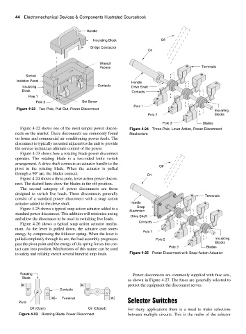
Figure 4-22 shows one of the most simple power discon- Figure 4-24 Three-Pole, Lever Action, Power Disconnect
nects on the market. These disconnects are commonly found Mechanism
on home and commercial air conditioning power feeds. The
disconnect is typically mounted adjacent to the unit to provide
the service technician ultimate control of the power.
Figure 4-23 shows how a rotating blade power disconnect
operates. The rotating blade is a two-sided knife switch
arrangement. A drive shaft connects an actuator handle to the
Off
pivot in the rotating blade. When the actuator is pulled
through a 90 arc, the blades connect. On
Figure 4-24 shows a three-pole, lever action power discon-
nect. The dashed lines show the blades in the off position.
The second category of power disconnects are those
designed to switch live loads. These disconnects generally
Terminals
consist of a standard power disconnect with a snap action
actuator added to the drive shaft. Handle
Snap
Figure 4-25 shows a typical snap action actuator added to a
Mechnism
standard power disconnect. This addition will minimize arcing
Drive Shaft
and allow the disconnect to be used in switching live loads.
Contacts
Figure 4-26 shows a typical snap action actuator mecha-
nism. As the lever is pulled down, the actuator cam stores
Pole 1
energy by compressing the follower spring. When the lever is
pulled completely through its arc, the load assembly progresses Pole 2 Insulating
past the pivot point and the energy of the spring forces the con- Blocks
Pole 3 Blades
tact cam into position. Mechanisms of this nature can be used
to safety and reliably switch several hundred amp loads. Figure 4-25 Power Disconnect with Snap-Action Actuator
Rotating Power disconnects are commonly supplied with fuse sets,
Blade
as shown in Figure 4-27. The fuses are generally selected to
protect the equipment the disconnect serves.
Contacts
Terminal
Pivot Selector Switches
Off (Open) On (Closed) For many applications there is a need to make selections
Figure 4-23 Rotating Blade Power Disconnect between multiple circuits. This is the realm of the selector