
Page 85 - Electromechanical Devices and Components Illustrated Sourcebook
P. 85
Chapter 4 Electrical Controls 47
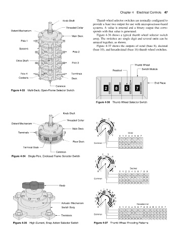
Knob Shaft Thumb wheel selector switches are normally configured to
provide a base two output for use with microprocessor-based
Threaded Collar systems. A value is entered and a binary output that corre-
Detent Mechanism sponds with that value is generated.
Figure 4-36 shows a typical thumb wheel selector switch
Main Deck
array. The switches are single digit and several units can be
Pole 1
arrayed together, as shown.
Figure 4-37 shows the outputs of octal (base 8), decimal
Spacers (base 10), and hexadecimal (base 16) thumb wheel switches.
Pole 2
Drive Shaft
Pole 3
Thumb Wheel
Switch Module
Readout
Pole 4 Terminals
Contacts Deck
End Piece
Common
2 8 5 7
Figure 4-33 Multi-Deck, Open-Frame Selector Switch
Figure 4-36 Thumb Wheel Selector Switch
Knob Shaft
3 4
Threaded Collar
Detent Mechanism 2 5
Main Deck 1 6
Terminals Octal
0 7 0 1 2 3 45 6 7
0 1 0 1 0 1 0 1
Rear Deck 0 0 1 1 0 0 1 1
Common
0 0 0 0 1 1 1 1
Terminal Deck 0 00 0 0 0 0 0
Common
4 5
Figure 4-34 Single-Pole, Enclosed Frame Selector Switch 3 6
2 7
1 8
Decimal
0 9 0123456789
0 1 0 1 0 1 0 1 0 1
0 0 1 1 0 0 1 1 0 0
Common
0 0 0 0 1 1 1 1 0 0
0 0 0 0 0 0 0 0 1 1
Knob
7 8
6 9
5 A
4 B
3 C
2 D
Actuator Mechanism
1 E Hexadecimal
Switch Body 0 F 0 12 3 4 5 6 7 8 9 A BC DE F
0 1 0 1 0 1 0 1 0 1 0 1 0 1 0 1
0 0 1 1 0 0 1 1 0 0 1 1 0 0 1 1
Common
Terminals 0 0 0 0 1 1 1 1 0 0 0 0 1 1 1 1
0 0 0 0 00 0 0 1 1 1 1 1 1 1 1
Figure 4-35 High-Current, Snap Action Selector Switch Figure 4-37 Thumb Wheel Encoding Patterns