
Page 83 - Electromechanical Devices and Components Illustrated Sourcebook
P. 83
Chapter 4 Electrical Controls 45
Handle
Knob
Lever
Contact Cam
Actuator Cam Blade
Drive Shaft
Roller Brass Thumb Nut
Follower
Off (Open) Brass Hex Nut
Follower Spring Brass Flat
Washer
Shaft Guide
Contact
Shaft Pivot
Shaft
On (Closed)
Ready
Base
Figure 4-26 Snap-Action Mechanism for Power Disconnect
Long Brass Screw
Terminals Short Brass Screw
Handle
Actuator
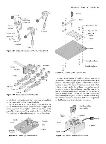
Figure 4-29 Selector Switch Exploded View
Fuses
Another simple method of building a selector switch is to
use a banana jumper configuration, as shown in Figures 4-30
and 4-31. The common jack is placed at the center of a circu-
lar array of jacks. The radius of the array is 0.75 inch, which
Pole 1 is the center spacing of a standard dual banana plug. A short-
Pole 2 ing wire is added to the dual banana plug. The plug can be
used to as the selector by simply pulling it out and reinserting
Pole 3
into a different position. It should be noted that the center-to-
Figure 4-27 Power Disconnect with Fuse Set
center spacing of the jacks that make up the circular array
should have a dimension other than 0.75 inch. This prevents
switch. These switches typically have a common terminal that the dual banana plug from being miss connected.
can be connected to several output terminals.
Figures 4-28 and 4-29 show a simple blade-type selector
switch. The blade and contacts are simple strips of copper, that Dual Banana Plug
are screwed to an insulating base. Terminals are placed at the Shorting Wire
ends of the strips. An insulating handle is affixed to the blade.
The blade may be adjusted to contact any one of the outputs.
Banana Common
Jacks
Outputs
E F
Handle
Terminals D
Blade Panel
A
Base COM.
C Cabinet
B
Contacts
Common
Terminal Input
Figure 4-28 Blade-Type Selector Switch Figure 4-30 Banana Jumper Selector Switch