
Page 88 - Electromechanical Devices and Components Illustrated Sourcebook
P. 88
50 Electromechanical Devices & Components Illustrated Sourcebook
Harsh environments, such as the plant floor, require espe-
Actuators
cially rugged limit switches. These units are generally
referred to as industrial limit switches. They generally have
high-impact housings which are impervious to oil, water, and
many chemicals. Figure 4-44 shows two industrial limit
switches, with a center-loaded lever arm and one with latch-
ing lever arms.
For precise control of mechanical movement, a micrometer-
adjustable limit switch may be configured, as shown in
Figure 4-45. This arrangement provides control of the switch Individual
down to 0.001inch. Micrometer adjustable limit switches are Limit Switches
commonly found in modern machine tools. Through Bolts
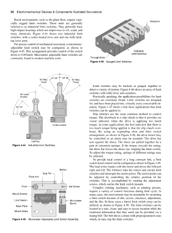
Figure 4-46 Ganged Limit Switches
OP 30° OP 30°
60° Max. 60° Max.
Travel Travel
Limit switches may be stacked, or ganged, together to
detect a variety of motion. Figure 4-46 shows an array of limit
switches with roller lever arm actuators.
90° Latch
Position Practically speaking, the application possibilities for limit
switches are extremely broad. Limit switches are designed
for, and have been placed into, virtually every conceivable sit-
OP 45° uation. Figure 4-47 shows a few basic applications that limit
switches can be applied to.
Slip clutches are the most common method to control
torque. The drawback to a slip clutch is that it provides no
visual indicator when the drive is applying too much
Center Loaded torque. In some applications, the first indicator that there is
too much torque being applied is that the slip clutch over-
heats. By using an expanding shoe and limit switch
arrangement, as shown in Figure 4-48, the drive motor may
be controlled or an alarm may be sounded. The drive bar
Latching acts against the shoes. The shoes are pulled together by a
Figure 4-44 Industrial Limit Switches pair of extension springs. If the torque exceeds the rating,
the drive bar forces the shoes out, tripping the limit switch.
To adjust the torque rating, springs of different ratings may
be selected.
To provide local control of a long conveyer belt, a limit
switch travel control can be configured as shown in Figure 4-49.
The lead screw rotates with the motor and drives the follower
Motion right and left. The follower trips the retract and extend limit
Stop Pin switches and interrupts the motor power. The travel points can
Pivot Arm be adjusted by controlling the relative position of the
switches. This is accomplished by rotating the adjustment
screws, which carries the limit switch mounts.
Pivot Set Screw
Complex rotating machinery, such as printing presses,
require a variety of control functions during their cycle. In
Mount Screws many cases, the environment may be unsuitable for mounting
20 Amp. 220 VAC, 1 HP
10 Amp. 120 VDC 0 a limit switch because of dirt, access, clearance, adjustment,
Limit Switch .1 Micrometer
Barrel
.2 and the like. In these cases a barrel limit switch array can be
Base Plate utilized, as shown in Figure 4-50. The limit switches can be
located in a safe, clean, and easy to access location while the
Mount Holes rotational information that they need can be provided via a
timing belt. The belt drives a drum with preprogrammed cams
Figure 4-45 Micrometer Adjustable Limit Switch Assembly which, in turn, trip the limit switches.