
Page 92 - Electromechanical Devices and Components Illustrated Sourcebook
P. 92
54 Electromechanical Devices & Components Illustrated Sourcebook
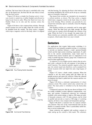
and float. The lower limit of the arm is controlled with a stop with the housing. By adjusting the float to the bottom or the
pin. As the liquid rises, the float lifts the arm which, in turn, top during installation, the switch can be set up as a normally
trips the limit switch. open or a normally closed unit.
Figure 4-55 shows a simple free floating switch. A mer- Top mount float switches are intended to be mounted in
cury switch is sealed into a rubber bladder and allowed to a vertical position, as shown. The float carries a magnet
hang freely from its cable. When the fluid level rises, the which trips a magnetic switch in the body when it is at the
bladder floats on its side and the mercury closes the top of the housing. These switches can generally be con-
switch. verted from normally open to normally closed by flipping
Figure 4-56 shows a few common float switches. Through the float over.
mount switches are used in tanks where the switch can only Free floating switches are commonly used in sump appli-
be installed from the outside. The float carries a magnet, cations. When the fluid level gets high enough, the float
which trips a magnetic switch in the body when it is aligned switch turns on a pump which discharges the contents of the
sump. When the level is low enough, the pump shuts off.
These switches are commonly available with a switched AC
receptacle, which makes them very easy to install.
Contactors
For applications that require high-current switching, it is
impractical to use manually-actuated switches. It is necessary
Cable
to provide an interface between a small, operator-friendly
switch and the high-current switching requirement. In addi-
tion to the current considerations, many loads must be
Rubber
Cement Seal switched from remote locations and it is impractical or too
costly to install long runs of heavy gauge wire. Contactors are
Rubber used for these applications.
Bladder
A contactor is a set of high-current contacts that are actu-
Mercury
Switch ated with a solenoid for the sole purpose of providing an
on/off function. The solenoid typically requires a low volt-
Off Position On Position age, low current signal and, therefore, can be actuated from
remote locations with very light wire and a high degree of
Figure 4-55 Free Floating Switch Assembly
safety.
Figure 4-57 shows a knife switch contactor. When the
solenoid is off, the return spring pulls the blade into an
upright position and opens the contactor. When the solenoid
is energized, the blade is pulled into the contacts and the con-
NPT Thread
Float Pivot tactor is closed.
Figure 4-58 shows a schematic representation of a basic
Switch contactor circuit. The control switch only controls the coil
Housing power. The main power is switched on by the heavy-duty
Float contacts.
Side Mount
Commercial contactors, like the one shown in Figure 4-59,
NPT Thread
are readily available in many different configurations, volt-
Top Mount
Switch ages, and currents. Commercial contactors are commonly
Housing
available with current ratings as high as 200 amps per pole.
Float
Free Floating A four-pole contactor, with 125 amp contacts, can be wired
in parallel and provide as much as 500 amps of switching
Cable Snap Ring
capacity, all from a very compact and inexpensive package.
Figure 4-60 shows a sectional view of a typical commer-
AC Input
cial contactor. Take note of the visual indicator that can also
double as a manual override. This is a particularly useful fea-
Switched ture to service technicians.
Output Some contactors are supplied with auxiliary contacts to
Figure 4-56 Commercial Float Switches make setting up the controls a little easier. The schematic