
Page 91 - Electromechanical Devices and Components Illustrated Sourcebook
P. 91
Chapter 4 Electrical Controls 53
Magnetic Switches Solder Terminals
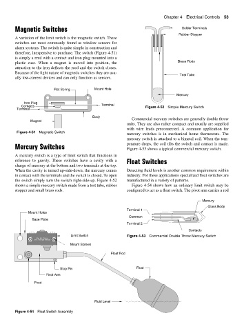
Rubber Stopper
A variation of the limit switch is the magnetic switch. These
switches are most commonly found as window sensors for
alarm systems. The switch is quite simple in construction and
therefore, inexpensive to purchase. The switch (Figure 4-51)
is simply a reed with a contact and iron plug mounted into a
plastic case. When a magnet is moved into position, the Brass Rods
attraction to the iron deflects the reed and the switch closes.
Because of the light nature of magnetic switches they are usu-
Test Tube
ally low-current devices and can only function as sensors.
Flat Spring Mount Hole
Mercury
Iron Plug
Contacts Terminal Figure 4-52 Simple Mercury Switch
Terminal
Body
Magnet Commercial mercury switches are generally double throw
units. They are also rather compact and usually are supplied
with wire leads preconnected. A common application for
Figure 4-51 Magnetic Switch
mercury switches is in mechanical home thermostats. The
mercury switch is attached to a bimetal coil. When the tem-
perature drops, the coil tilts the switch and contact is made.
Mercury Switches Figure 4-53 shows a typical commercial mercury switch.
A mercury switch is a type of limit switch that functions in
reference to gravity. These switches have a cavity with a Float Switches
charge of mercury at the bottom and two terminals at the top.
When the cavity is turned up-side-down, the mercury comes Detecting fluid levels is another common requirement within
in contact with the terminals and the switch is closed. To open industry. For these applications specialized float switches are
the switch simply turn the switch right-side-up. Figure 4-52 manufactured in a variety of patterns.
shows a simple mercury switch made from a test tube, rubber Figure 4-54 shows how an ordinary limit switch may be
stopper and small brass rods. configured to act as a float switch. The pivot arm carries a rod
Mercury
Glass Body
Terminal 1
Mount Holes
Common
Base Plate
Terminal 2
Contacts
Limit Switch Figure 4-53 Commercial Double Throw Mercury Switch
10 Amp. 120 VDC
20 Amp. 220 VAC, 1 HP
Mount Screws
Float Rod
Stop Pin Float
Pivot Arm
Pivot
Fluid Level
Figure 4-54 Float Switch Assembly